Drainage tile flow regulator

a flow regulator and draining tile technology, applied in mechanical equipment, valves, transportation and packaging, etc., can solve the problems of affecting crop yield, tile lines typically continue to drain without means to control or adjust the flow, and affecting crop yield

Inactive Publication Date: 2004-07-29
CHARLES J SCHAFER REVOCABLE TRUST +1
View PDF8 Cites 3 Cited by
  • Summary
  • Abstract
  • Description
  • Claims
  • Application Information

AI Technical Summary

Benefits of technology

[0009] It is another object of the invention to provide a way to keep the water table high in the soil over the winter months so that nutrients and nitrates will not be lost but can break down naturally in the soil or be maintained until needed in the spring;
[0010] It is also an object of the invention to allow the water table to be dropped as low as possible prior to harvest to allow access to the field and to minimize compaction of the soil by large equipment and also prior to planting to allow the soil to warm and encourage deep root growth and, again, to allow access to the field.

Problems solved by technology

Unfortunately, when moisture levels and the season result in a need for more water in the soil, the tile lines typically continue to drain without means to control or adjust the flow.
In this manner, efficient water removal by tile lines can be detrimental to the crop either by depriving the plants of moisture or by allowing nitrates and other nutrients used by plants to flow out of the soil before use by plants or before sufficient time has passed to allow them to break down naturally.

Method used


Image

  • Drainage tile flow regulator
  • Drainage tile flow regulator
  • Drainage tile flow regulator

Examples


Embodiment Construction

)

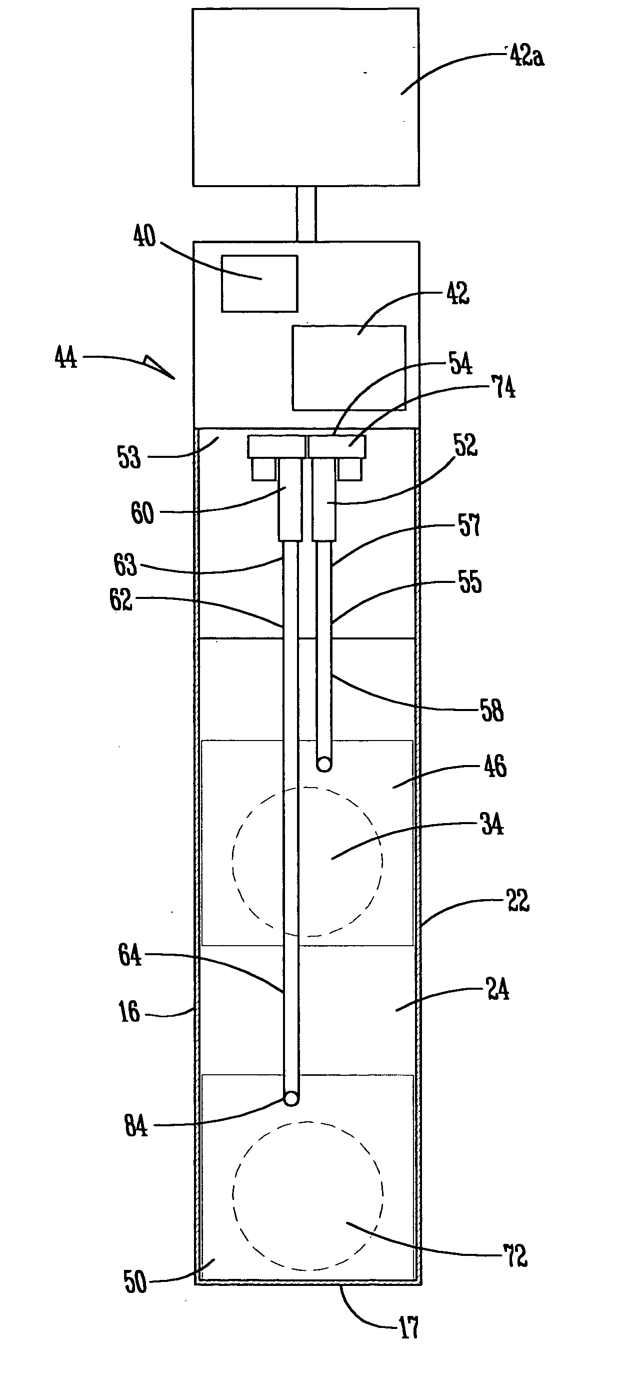
[0028] As shown generally in FIG. 1, a tile line 10 is buried under soil in a field, with a general slope toward an outlet 12 and including a tile line flow regulator shown at 14. The flow regulator 14 (as shown in FIG. 2) comprises a housing 16. In one embodiment the housing 16 comprises a bottom 17, a front panel 18, a back panel 20, and two side panels 22. However, the housing 16 can be of any shape such as cylindrical as long as a bottom 17 is present.

[0029] A partition 24 divides said housing 16 into a front portion 25 and a back portion 27. Two opposed and aligned openings, 30 and 32, are provided near the bottom 17 of said housing 16. Said partition 24 comprises at least one aperture 34 not necessarily aligned with said outlet 12. The invention further comprises means for securing said partition 35 in position between said front portion 25 and said back portion 27. Preferably, means for securing said partition 35 is in the form of tracks mounted in said housing 16.

[0030] In ...


PUM


Abstract

The tile flow regulator disclosed is used for regulating the level of water in the fields of an agricultural operation according to seasonal needs by a mechanism for adjusting the outflow of water from the tile line. The regulator includes a housing through which water from the tile line is directed and in which a partition with at least one aperture is positioned. At least one vertically movable gate is associated each aperture and with a motor, an electric cylinder, and at least one actuator bar such that, upon actuation of the motor, the gate moves to either open or close the aperture. If two apertures are included, the regulator can be fully open (both apertures open), fully closed (both apertures closed), or partially open (bottom aperture open, top one closed) to achieve the desired moisture level. Dates on which the gates will be moved can be pre-selected by remote signaling.

Description

[0001] This is a continuation-in-part of application Ser. No. 10 / 164,674 filed Jun. 6, 2002 for Drainage Tile Flow Regulator.[0002] 1. Field of the Invention[0003] The present invention relates in general to regulating the level of water in the fields of an agricultural operation and, more particularly, to a system wherein the level of moisture in the soil above a buried tile line is regulated according to seasonal needs by a pre-set calendar and mechanism for regulating the outflow of water from the tile line.[0004] 2. Description of the Prior Art[0005] It is known in the art to use a variety of machines and apparatuses to increase or decrease moisture in soil used for agrarian purposes. Some of these machines include the use of aquifers, irrigation ditches and canals, use of overhead sprinkler irrigation, terracing for directing the flow of water while maintaining top soil and some moisture in the soil on a hill, and the laying of underground tile lines into which water will drain...

Claims


Application Information

Patent Timeline
IPC IPC(8): A01G25/16
CPCA01G25/16Y10T137/86389Y10T137/86445
Inventor SCHAFER, CHARLIE J.BEEBOUT, LEO E.LITTLER, WILLIAM IV
Owner CHARLES J SCHAFER REVOCABLE TRUST
Why Eureka
Try Eureka