
Improvements in excavator teeth

Inactive Publication Date: 2004-06-10
MEYERS THOMAS ANTHONY
View PDF32 Cites 98 Cited by
  • Summary
  • Abstract
  • Description
  • Claims
  • Application Information

AI Technical Summary

Benefits of technology

0029] According to a further aspect of this invention there is provided a lock for releasably attaching a wear member to a mounting nose of an excavator bucket, said lock comprising: a retaining member having a head portion and a screw-threaded shaft; and an elongate body member having a non-circular cross section, said body member being adapted for removable insertion in a lock aperture of complementary cross section in the mounting nose, said body member including a screw-threaded aperture to receiva

Problems solved by technology

As the various components wear, the locking pins can loosen thereby increasing the risk of loss of a digging point or an entire digging tooth assembly.
Despite many prior art attempts to improve the mounting of an adaptor to a nose, most of these proposals suffer from one or more deficiencies.
Because the tongues themselves are unsupported, they possess a limited capacity to resist rotational moment forces.
Because the side tongues are recessed to accommodate the side rail portions, the robustness of the side tongues is somewhat compromised.
This structure is heavily reliant on the locking pin to resist rotational moment forces however it is considered that this configuration may be prone to failure in the rear portion of the adaptor.
While adequ

Method used


Image

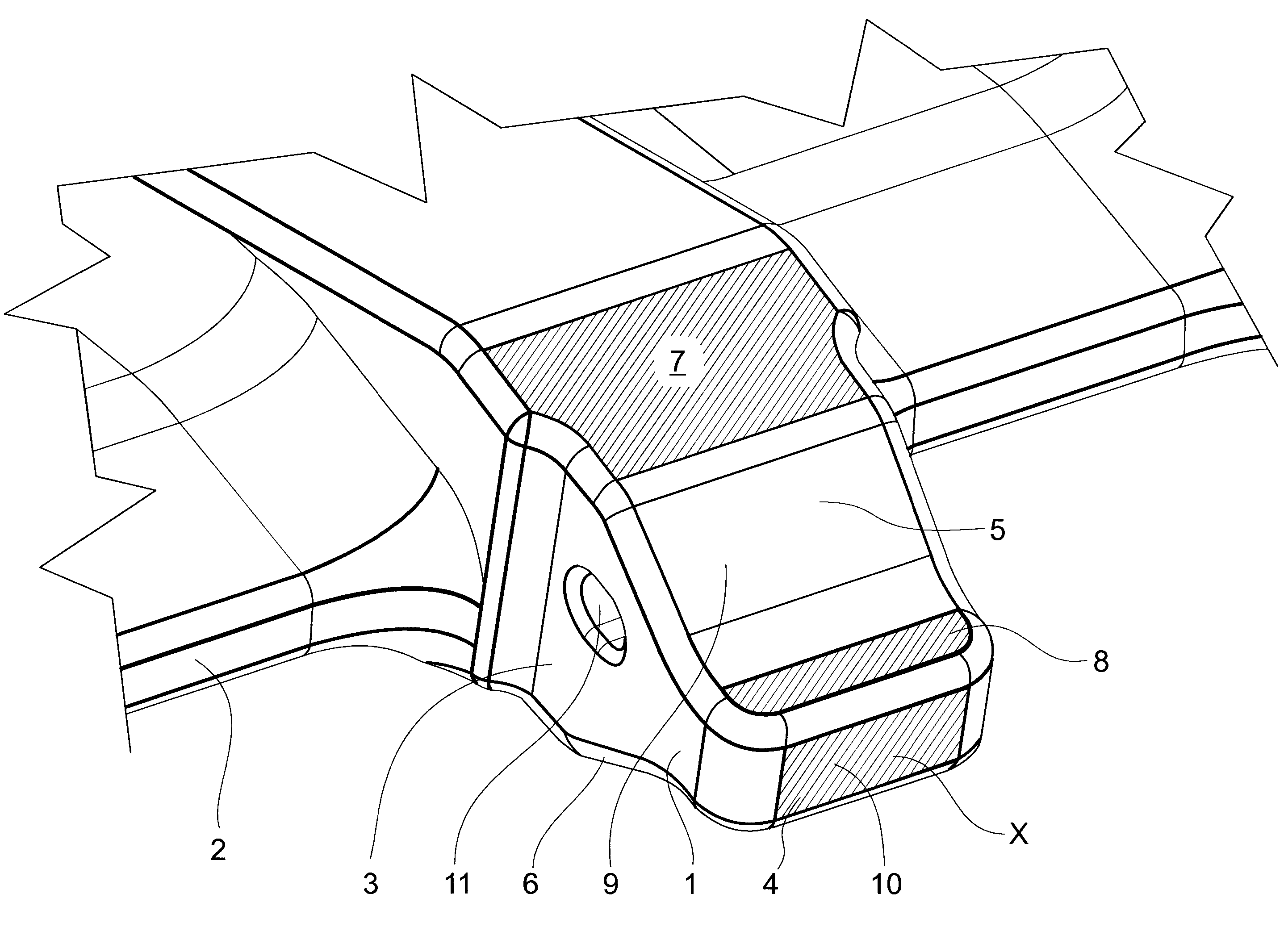
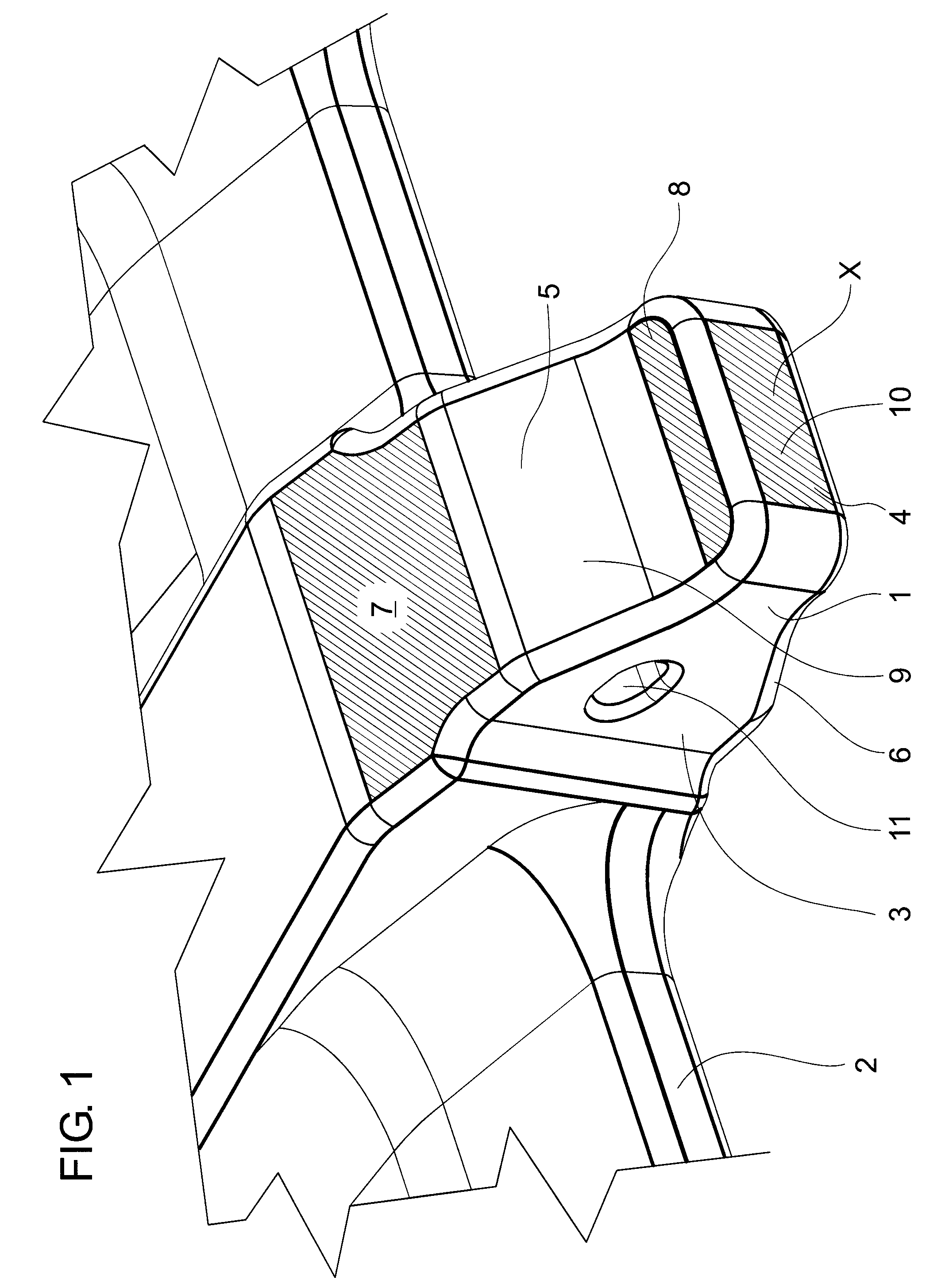
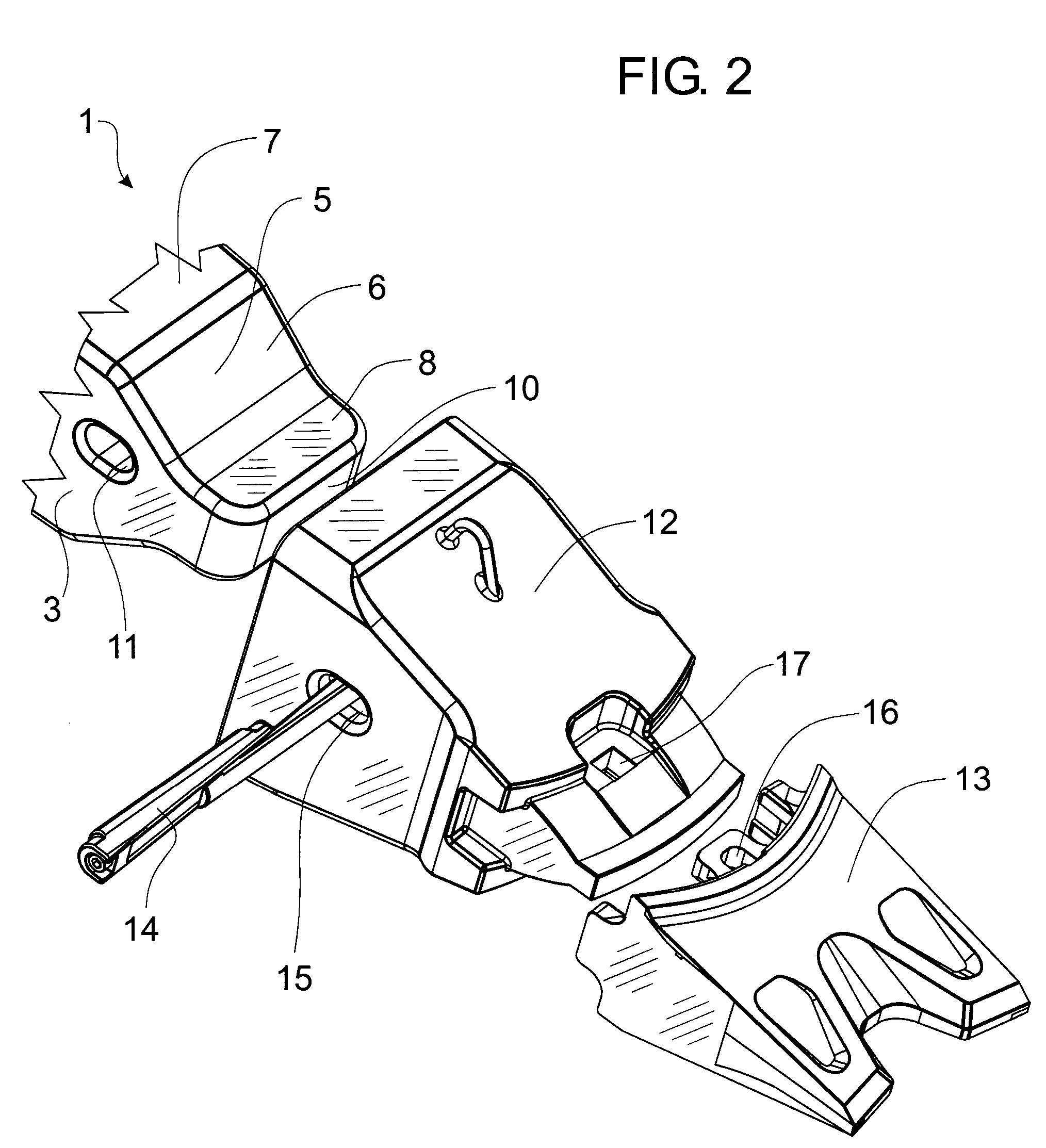
  • Improvements in excavator teeth
  • Improvements in excavator teeth
  • Improvements in excavator teeth

Examples


Example

Background of Invention

[0001] This invention is concerned with improvements in excavator teeth for earth excavating devices.

[0002] The invention is concerned particularly, although not exclusively, with the mounting of excavator teeth adaptors to adaptor noses on an excavating device such as an excavator bucket or the like.

[0003] Excavating teeth mounted to the digging edge of excavator buckets and the like generally comprise a replaceable digging point, an adaptor body and an adaptor nose which is secured by welding or the like to the digging edge of a bucket or the like. The adaptor has a socket-like recess at its rear end to receivably locate a front spigot portion of the adaptor nose and a locking pin extends through aligned apertures in the adaptor and nose to retain the adaptor in position.

[0004] In use, excavator teeth are subjected to extensive load forces along a longitudinal axis of a tooth as well as in vertical and transverse directions. A snug fit is required between th...


PUM


Abstract

Abstract of the Disclosure An excavator tooth system comprises a mounting nose having a projecting spigot and a wear member (12) having at one end a socket (18), the socket (18) being defined by spaced side walls and upper and lower walls converging from a rearwardly facing socket opening to a forward end of the socket. Each of the upper and lower walls comprises a forward bearing face (8a) and a rear bearing face (7a) separated by a forwardly convergent intermediate face. The front and rear bearing faces (8a,7a) are substantially parallel to a longitudinal axis (50) of the wear member and engage corresponding bearing faces (8,7) in said spigot.

Description

Detailed Description of the InventionBackground of Invention[0001] This invention is concerned with improvements in excavator teeth for earth excavating devices.[0002] The invention is concerned particularly, although not exclusively, with the mounting of excavator teeth adaptors to adaptor noses on an excavating device such as an excavator bucket or the like.[0003] Excavating teeth mounted to the digging edge of excavator buckets and the like generally comprise a replaceable digging point, an adaptor body and an adaptor nose which is secured by welding or the like to the digging edge of a bucket or the like. The adaptor has a socket-like recess at its rear end to receivably locate a front spigot portion of the adaptor nose and a locking pin extends through aligned apertures in the adaptor and nose to retain the adaptor in position.[0004] In use, excavator teeth are subjected to extensive load forces along a longitudinal axis of a tooth as well as in vertical and transverse directio...

Claims


Application Information

Patent Timeline
IPC IPC(8): E02F9/28
CPCE02F9/2825E02F9/2883E02F9/2833
Inventor MEYERS, THOMAS ANTHONYLESLIE, BRUCE ALEXANDERDEWIT, JOHN ROBERT
Owner MEYERS THOMAS ANTHONY
Learn More