Traffic light signal monitoring system

a technology of traffic light signal and monitoring system, which is applied in the direction of traffic control system, road vehicle traffic control, instruments, etc., can solve the problems of not being able to watch motor vehicles traveling through the intersection for other violations, traffic enforcement personnel must be positioned near, and other traffic infractions are missed

Inactive Publication Date: 2004-03-18
CARTER GREG
View PDF3 Cites 29 Cited by
  • Summary
  • Abstract
  • Description
  • Claims
  • Application Information

AI Technical Summary

Benefits of technology

0011] These and other objects of the present invention are met by a traffic light monitoring system that enables traffic enforcement personnel to monitor traffic light signal infractions while positioned at a distant or remote location from the intersection where they would otherwise not be able to see the color of the traffic light signal. The system, which is designed to be installed with existing traffic sig

Problems solved by technology

One drawback with simultaneously monitoring the illumination of the lights on the traffic light signal and the motor vehicle traffic is that the traffic enforcement personnel must be positioned near the intersection.
Another drawback with simultaneously monitoring the illumination of the traffic light signal and the motor vehicle traffic is that other traffic infractions are missed.
For example, if traffic enforcement personnel are continuously looking at the traffic light signal, he or she is unable to watch motor vehicles traveling through the intersection for other violations, such as operating a vehicle with defective equipment.

Method used


Image

  • Traffic light signal monitoring system
  • Traffic light signal monitoring system
  • Traffic light signal monitoring system

Examples


Embodiment Construction

)

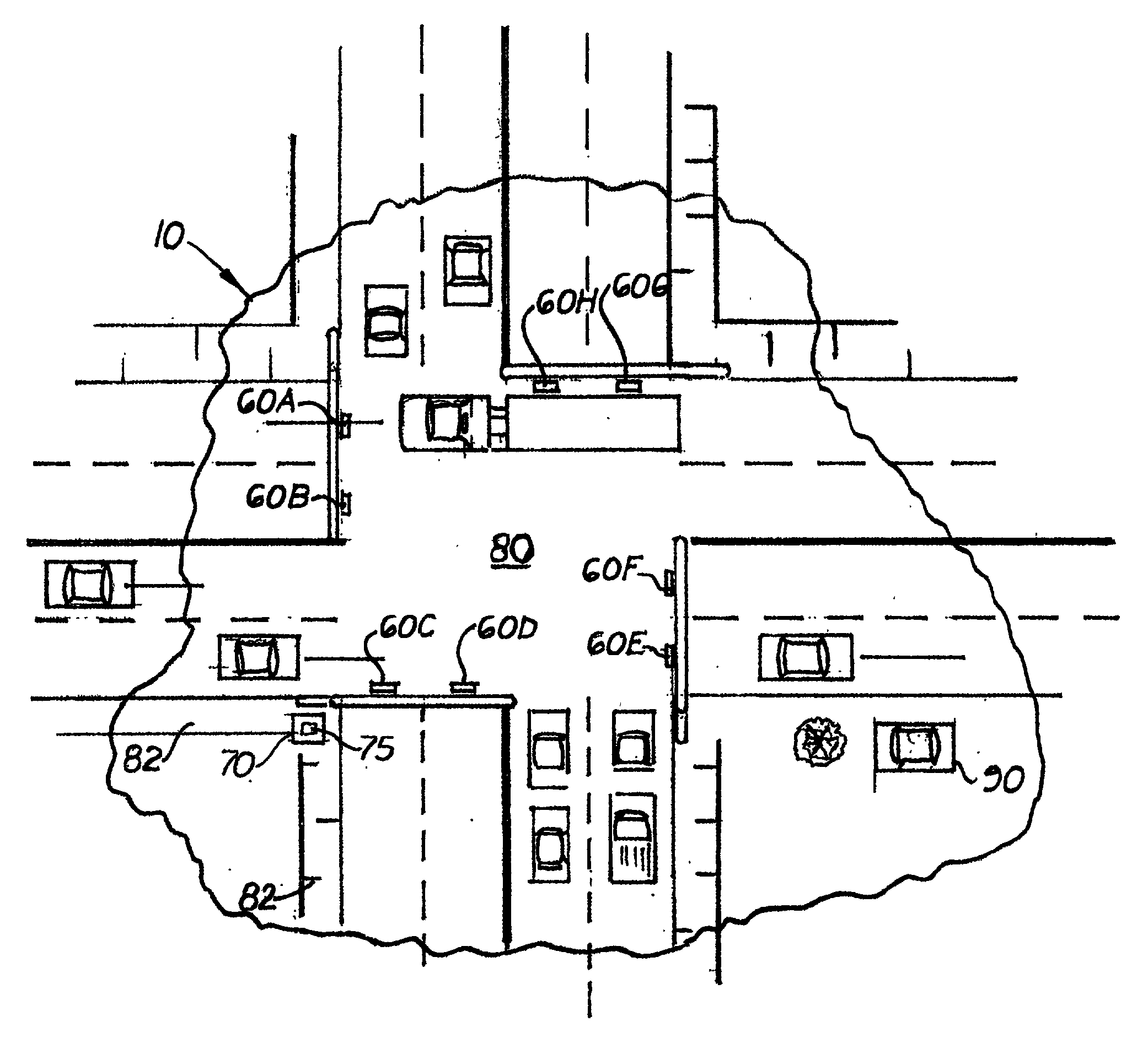
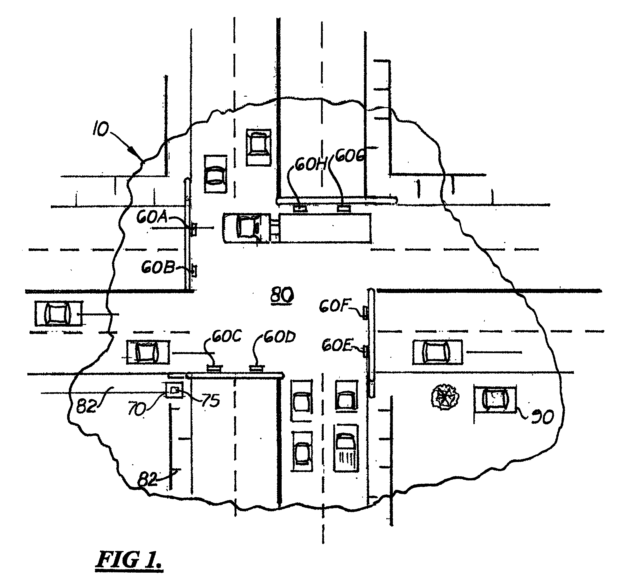
[0018] There is shown in the accompanying Figs. a traffic light monitoring system 10 and method that enables traffic enforcement personnel 90 to monitor the movement of traffic through an intersection 80 controlled by traffic signal lights 60 A-H for traffic light signal infractions while positioned at a distant location from the intersection 80 where they would otherwise not be able to see the color of a desired traffic light signal 60. During use, traffic enforcement personnel 90 are able to watch traffic travel through the intersection 80 without constantly viewing a specific traffic light signal 60. When the amber light circuit 61 on a monitored traffic light signal 60 is activated, a signal is transmitted to the traffic enforcement personnel 90 informing him to view the traffic light signal 60 and watch for violators.

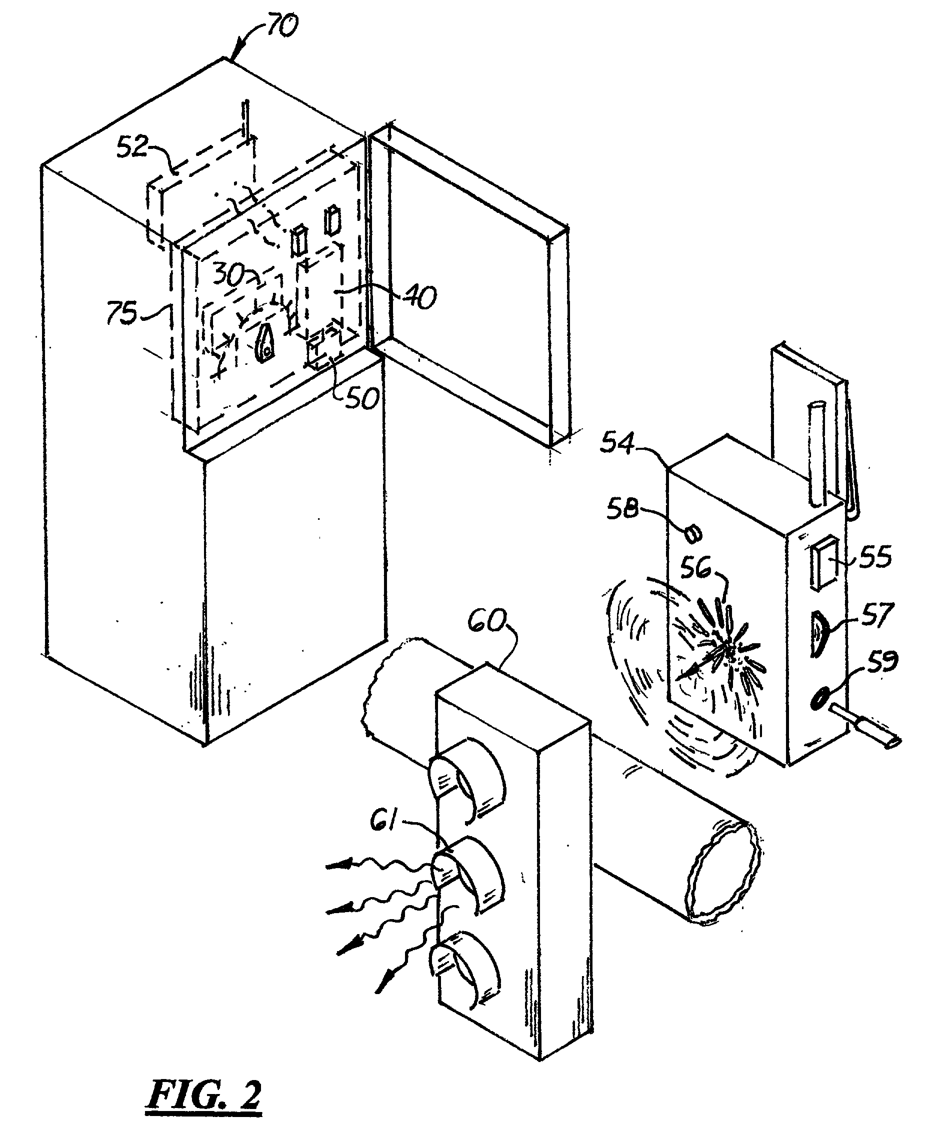
[0019] The system 10 is designed to be used with an existing traffic light control circuit 75 located in the cabinet 70 located on a curb or sidewalk 82 adjacent ...


PUM


Abstract

A traffic light signal monitoring system and method that enables traffic enforcement personnel to monitor the traffic moving through an intersection while positioned at a distant or remote location from the intersection where they would otherwise not be able to see the color of the traffic light signal. The system includes a distribution switch mounted in an existing traffic signal controller cabinet and electrically connected to the traffic light control circuits. The distribution switch is coupled to a radio transmitter. Connected to the transmitter is a tone generator that generates a tone when the amber light signal is activated. During use, traffic enforcement personnel positioned near the intersection are able to watch traffic travel through the intersection without looking directly at the lights activated on the traffic light. When the amber light circuit is activated, the tone is broadcast for approximately four seconds that informs the traffic enforcement personnel that the red light will be activated shortly and that their attention should be drawn to the flow of traffic through the intersection.

Description

[0001] 1. Field of the Invention[0002] This invention relates to traffic light signal monitoring systems, and more particularly, to systems used by traffic enforcement personnel to determine whether drivers and pedestrians are complying with traffic laws.[0003] 2. Description of the Related Art[0004] In many municipalities, traffic enforcement personnel routinely monitor traffic around traffic light signals for compliance with local traffic laws. In order to catch violators, traffic enforcement personnel are required to simultaneously monitor the illumination sequences of the green, amber and red lights on the traffic light signal and the movement of motor vehicles and pedestrians in the intersection. In order to issue citations to violators, the traffic enforcement personnel must know when the red light is illuminated and see the violation.[0005] One drawback with simultaneously monitoring the illumination of the lights on the traffic light signal and the motor vehicle traffic is t...

Claims


Application Information

Patent Timeline
IPC IPC(8): G08G1/017G08G1/095
CPCG08G1/095G08G1/0175
Inventor CARTER, GREG
Owner CARTER GREG
Why Eureka
Try Eureka