
Culture tube and angle rotor receiving the tube in centrifuge

a centrifuge and angle rotor technology, applied in centrifuges, laboratory glassware, instruments, etc., can solve the problems of insufficient preventive action, deformation, and insufficient movement of the cap 122, and achieve the effect of accelerating the centrifugal process and preventing the deformation

Active Publication Date: 2003-10-30
EPPENDORF HIMAC TECH CO LTD
View PDF17 Cites 14 Cited by
  • Summary
  • Abstract
  • Description
  • Claims
  • Application Information

AI Technical Summary

Problems solved by technology

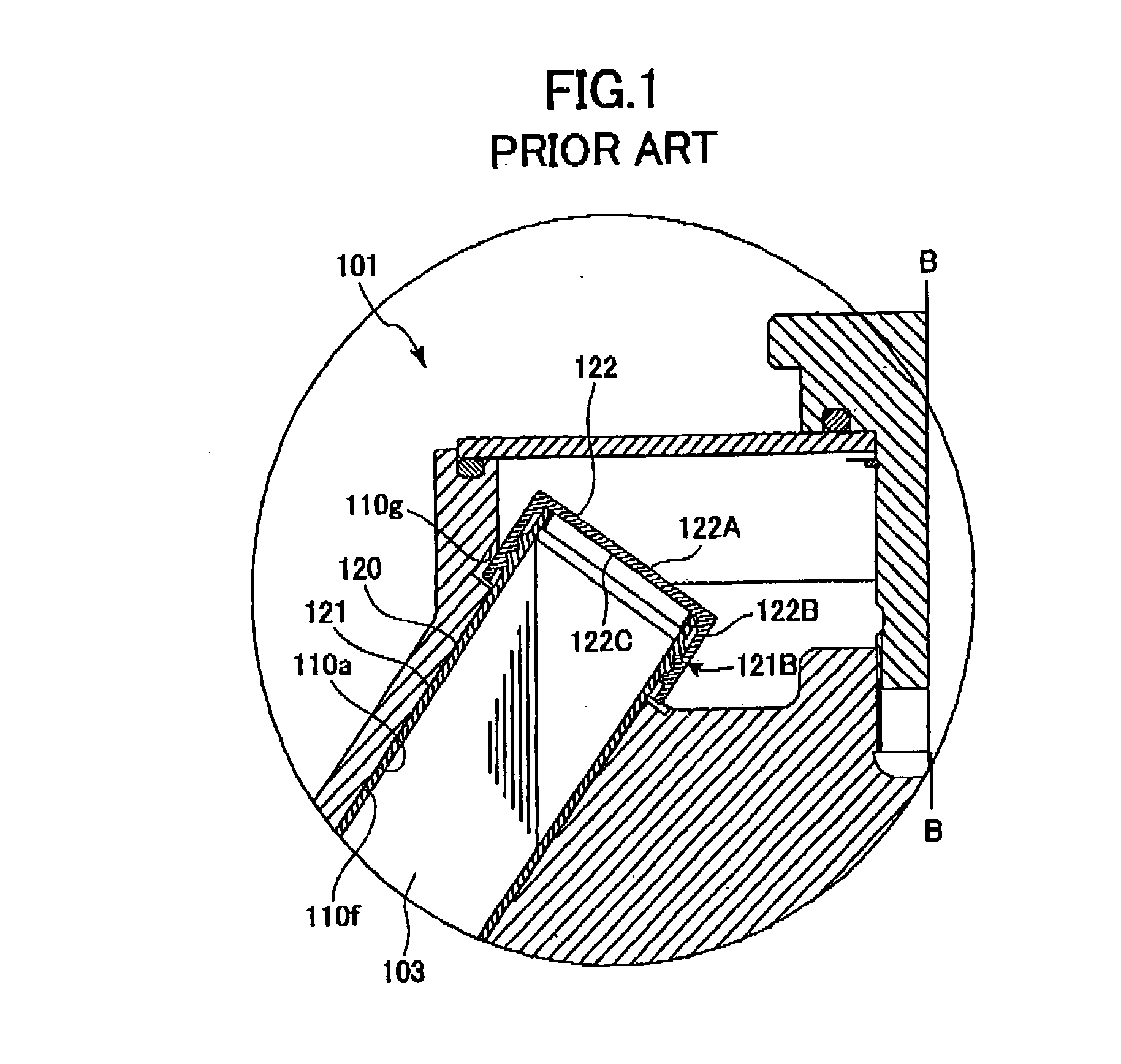
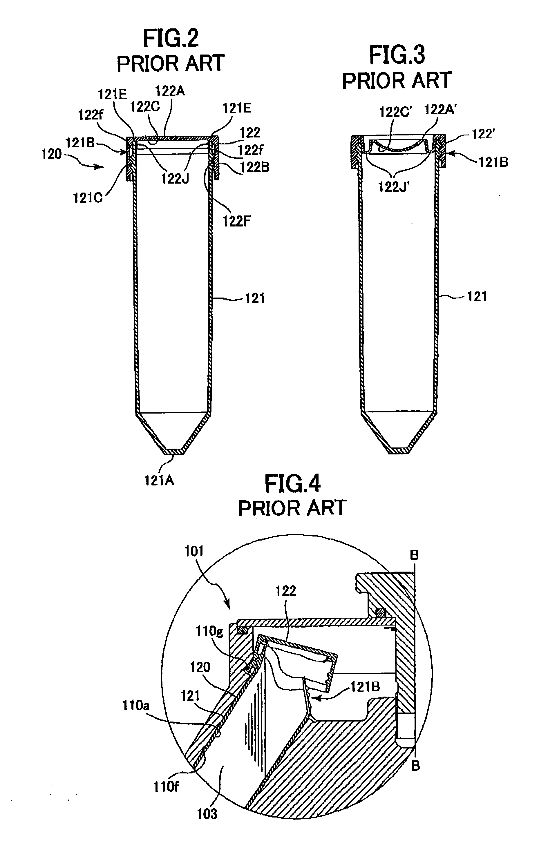
Therefore the conventional angle rotor 101 does not sufficiently prevent the cap 122 from moving and deforming.
The angle rotor 101 that accommodates the conventional culture / centrifugal tube 120 cannot be used at a high centrifugal acceleration so it has been difficult to speed up centrifuging process and processes that include centrifuging separation of the liquid sample 103.

Method used


Image

  • Culture tube and angle rotor receiving the tube in centrifuge
  • Culture tube and angle rotor receiving the tube in centrifuge
  • Culture tube and angle rotor receiving the tube in centrifuge

Examples


Embodiment Construction

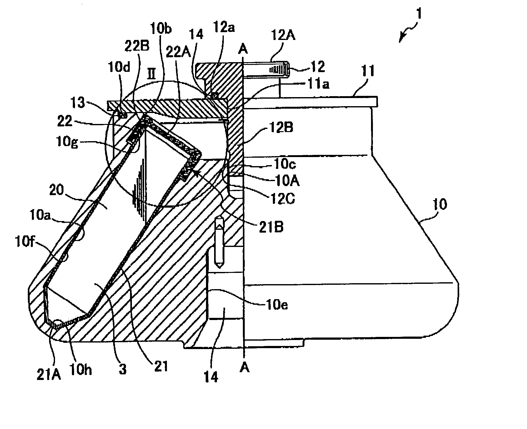
[0040] Next, a culture / centrifugal tube and an angle rotor according to an embodiment of the present invention will be described with reference to FIGS. 5 through 9. As shown in FIG. 1, an angle rotor 1 according to the present embodiment includes a rotor body 10, a cover 11, and a handle 12. The angle rotor 1 is provided in a centrifuge. The handle 12 is for attaching the cover 11 to the rotor body 10.

[0041] The rotor body 10 is connected to a motor (not shown) that is provided in the centrifuge. The motor drives the rotor body 10 to rotate about an rotation axis A-A. As shown in FIG. 7, the rotor body 10 is formed with a plurality of accommodation holes 10a disposed equidistance around the rotational axis A-A. As can be seen in FIG. 5, each of the accommodation holes 10a extends radially and downward from the rotational axis A-A to define a predetermined angle with respect to the rotational axis A-A. Said differently, the distance between the rotational axis A-A and the accommodat...


PUM

PropertyMeasurementUnit
centrifugal forceaaaaaaaaaa
perimeteraaaaaaaaaa
diameteraaaaaaaaaa

Abstract

A culture / centrifugal tube includes a tube and a cap. The cap has a disk portion and an annular portion that define an annular groove therebetween. The annular groove opens at a position level with the surface of the disk portion. The open end of the tube extends into the annular groove, with the open end of the vessel in abutment against the surface of the disk portion when the cap is fully engaged on the tube. An angle rotor that is used in a centrifuge is formed with an accommodation hole that receives the culture / centrifugal tube. The accommodation hole including a smaller-diameter tube accommodating portion that accommodates the tube and a larger-diameter cap accommodating portion that accommodates the cap. The cap accommodating portion includes a region that entirely encompasses a corresponding portion of the outer periphery of the annular portion of the cap.

Description

[0001] 1. Field of the Invention[0002] The present invention relates to an angle rotor and a culture / centrifugal tube used in the angle rotor.[0003] 2. Description of Related Art[0004] High-speed centrifuges are available in small sizes and with cooling functions and are used in a variety of fields, such as the medical, chemical, pharmaceutical, and genetic engineering fields. Disposable culture centrifuge tubes are used in the centrifuges.[0005] One type of centrifuge includes an angle rotor and a motor that produces drive force that rotates the angle rotor. A culture centrifuge tube filled with a sample liquid to be separated is mounted in the angle rotor, and the motor rotates the angle rotor. This type of centrifuge can rotate at maximum speeds of 5,000 to 14,000 RPMs. Some centrifuges can reach maximum speeds of up to 25,000 RPMs. Angle rotors are produced for various uses and rotated either under atmospheric pressure or within a vacuum.[0006] Here are some examples of angle ro...

Claims


Application Information

Patent Timeline
Patent Type & Authority Applications(United States)
IPC IPC(8): B01L3/14G01N1/00B04B5/02B04B5/04C12M1/26G01N1/10
CPCB01L3/5021B01L3/50825C12M33/10C12M23/08C12M23/38B04B5/0414
Inventor AIZAWA, MASAHARUMORITA, MASATAKA
Owner EPPENDORF HIMAC TECH CO LTD
Learn More