
Fine-stage automatic frequency compensation in post-detection BLUETOOTH applications

a fine-stage automatic and bluetooth technology, applied in the field ofpiconet wireless networks, can solve the problems of prone to errors in the conventional method of detecting frequency offset, incorrect adjustment of local oscillation, and different appearan

Inactive Publication Date: 2003-10-30
AVAGO TECH WIRELESS IP SINGAPORE PTE
View PDF8 Cites 32 Cited by
  • Summary
  • Abstract
  • Description
  • Claims
  • Application Information

AI Technical Summary

Problems solved by technology

Alternatively, the wireless communication can be accomplished with infrared (IR) transmitters and receivers, but this is less preferable because of the directional and visual problems often associated with IR systems.
However, this conventional method for detecting frequency offset is prone to errors, largely because the peak detection period is defined without the knowledge of the particular data pattern being received.
For instance, if a long data string of 0's or a long string of l's is received, the opposite peak can be correctly detected, causing the frequency offset to be erroneously calculated, resulting in incorrect adjustment of local oscillation.
Moreover, intersymbol interference may cause the peaks to appear differently depending on the particular data patterns.
Thus, if the opposite peaks are determined based on a data signal containing various interference effects, the detected offset will likely be inaccurate.

Method used


Image

  • Fine-stage automatic frequency compensation in post-detection BLUETOOTH applications
  • Fine-stage automatic frequency compensation in post-detection BLUETOOTH applications
  • Fine-stage automatic frequency compensation in post-detection BLUETOOTH applications

Examples


Embodiment Construction

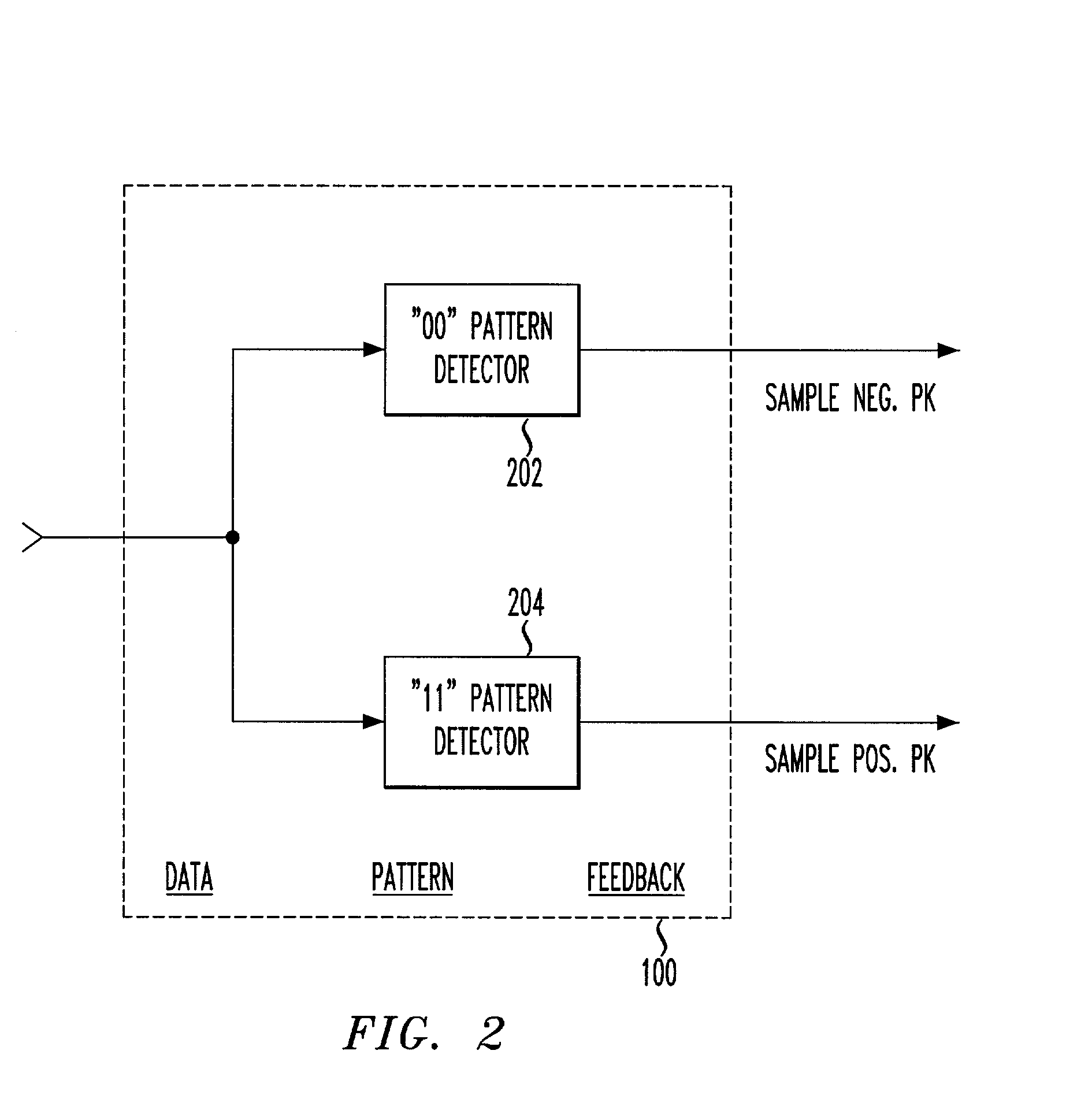
[0024] The present introduces a data-pattern feedback mechanism in the peak detection process of automatic frequency compensation.

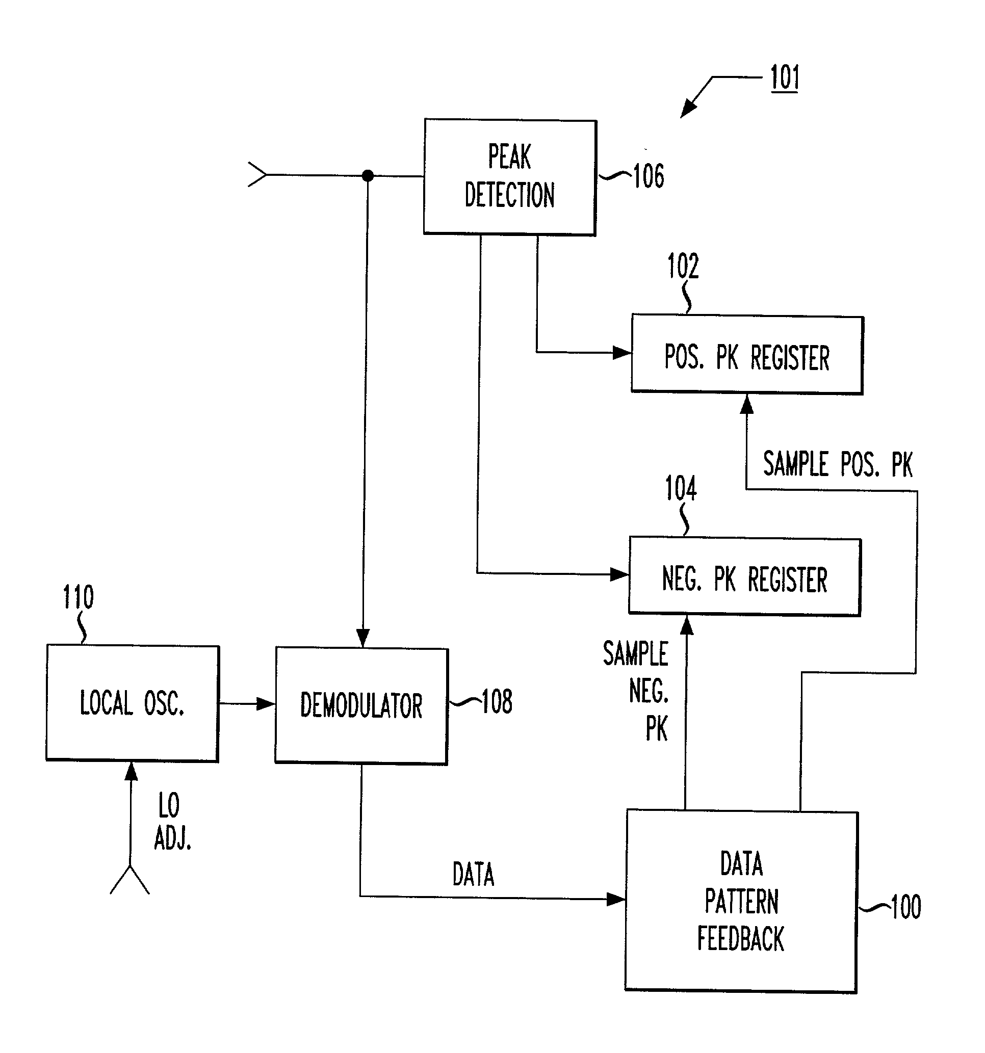
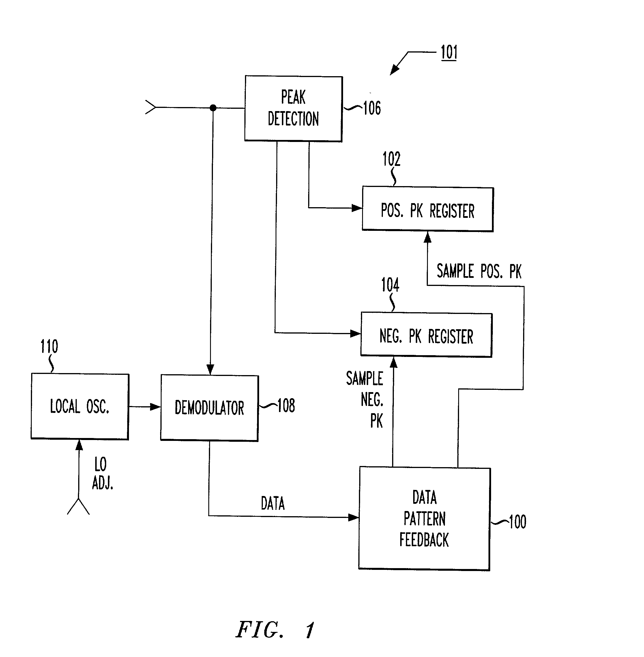
[0025] FIG. 1 shows a block diagram of an exemplary fine-stage automatic frequency compensation (AFC) system including data pattern feedback in peak detection, in accordance with the principles of the present invention.

[0026] In particular, FIG. 1 shows an automatic frequency compensation system 101 including a peak detection module 106 and a data pattern feedback module 100. A processor may be used to comprise and / or control the various digital components shown in FIG. 1. The processor may be, e.g., a suitable digital signal processor (DSP), microprocessor, or microcontroller.

[0027] The automatic frequency compensation system 101 comprises an otherwise conventional demodulator 108, local oscillator 110, and peak detection module 106. The AFC system 101 also includes suitably sized positive peak register 102 and negative peak register 104.

[0028] The peak ...


PUM


Abstract

A data-pattern feedback mechanism is introduced into the peak detection process of an automatic frequency compensation system in a Gaussian Frequency Shift Keying (GFSK) modulated system, providing fast and accurate fine-stage automatic frequency compensation (AFC). Maximum positive and negative peak registers are updated with new values as necessary based on detection during a sequence of identical binary bit values (e.g., during a "00" for detection of maximum negative peak frequency, or during a "11" for detection of maximum positive peak frequency), in a particular data frame. As soon as an initial value is determined for both the maximum positive and negative peak frequencies (e.g., after the first occurrence of a "11" and a "00", in any order), fine-stage automatic frequency compensation can be initiated. Subsequent adjustments to the VCO of the local oscillator will further refine the frequency offset towards the ideal of zero. Quick determination of the maximum positive and negative peak frequencies is made based on data pattern feedback in accordance with the principles of the present invention, allowing for a fast and accurate fine-stage automatic frequency compensation adjustment of a local oscillation clock signal.

Description

[0001] 1. Field of the Invention[0002] The present invention relates to piconet wireless networks. More particularly, it relates to frequency compensation in radio frequency (RF) devices.[0003] 2. Background of Related Art[0004] Piconets, or small wireless networks, are being formed by more and more devices in many homes and offices. In particular, a popular piconet standard is commonly referred to as a BLUETOOTH.TM. piconet. Piconet technology in general, and BLUETOOTH technology in particular, provides peer-to-peer communications over short distances. The BLUETOOTH.TM. specification Version 1.1 is available at www.bluetooth.com, and is explicitly incorporated herein by reference.[0005] The wireless frequency of piconets may be 2.4 GHz as per BLUETOOTH standards, and / or typically have a 20 to 100 foot range. The piconet RF transmitter may operate in common frequencies which do not necessarily require a license from the regulating government authorities, e.g., the Federal Communicat...

Claims


Application Information

Patent Timeline
Patent Type & Authority Applications(United States)
IPC IPC(8): H04L12/56H04L27/00H04L27/16H04L27/233
CPCH04L27/16H04L27/2332H04W84/18H04L2027/0065H04W24/00H04L2027/0046
Inventor HANSEN, ERIC JOHNLUO, WENZHEMA, ZHIGANGMCDOWELL, RICHARD L.
Owner AVAGO TECH WIRELESS IP SINGAPORE PTE
Learn More