Overhead door lock system and control unit therefor

Inactive Publication Date: 2003-10-09
SHOEMAKER RODNEY
View PDF4 Cites 13 Cited by
  • Summary
  • Abstract
  • Description
  • Claims
  • Application Information

AI Technical Summary

Benefits of technology

[0011] It is a further object of the present invention to provide a lock mechanism which is designed with an arm capable of extending into a trackway normally designed to receive one or more rollers on an overhead sectional door. In this latter condition, the arm will block movement of the door rollers and thereby preclude movement of the door to an opened position. The lock mechanism also permits means for withdrawal of the arm from its blocking position in the track thereby allowing free movement of the door rollers and, hence, the door mounted in said trackway to the opened position.
[0012] It is an additional object of the present invention to provide a method of controlling the movement of a garage door through a control module which operates in conjunction with a lock mechanism and thereby allows operation of a door opener only if the lock is in an unlocked condition to thereby open an overhead door. In other words, the door can open or close only if the lock mechanism is unlocked.
[0013] It is another salient object of the present invention to provide a method for obtaining a security locking action for an overhead sectional door in conjunction with an opener for the door and where the condition of the lock is sensed and movement of the door is controlled in response thereto.
[0015] The present invention provides a door lock system primarily for use with overhead doors, such as overhead sectional garage doors, in which there is provided a lock mechanism, as well as a relatively simple lock control circuit, frequently referred to as a "lock control module". This module is relatively simple and is capable of controlling the security functions of the system of the present invention.
[0020] The locking mechanism of the invention is effective, in that it literally operates without a locking pin or lock engaging elements, such as cams, pawls, and the like. Rather, the locking mechanism causes movement of the locking bar or arm, which is shiftable into and out of the track, defining a pathway for rollers on the door itself.

Problems solved by technology

However, in many cases, the locking effects offered by an operator are limited.
Where security is necessary for access to an installation, these operators usually do not have a sufficient locking capacity or locking capability.
Consequently, it is sometimes necessary to provide an additional locking mechanism which operates in conjunction with, but which may be independent of, the door operator itself.

Method used


Image

  • Overhead door lock system and control unit therefor
  • Overhead door lock system and control unit therefor
  • Overhead door lock system and control unit therefor

Examples


Embodiment Construction

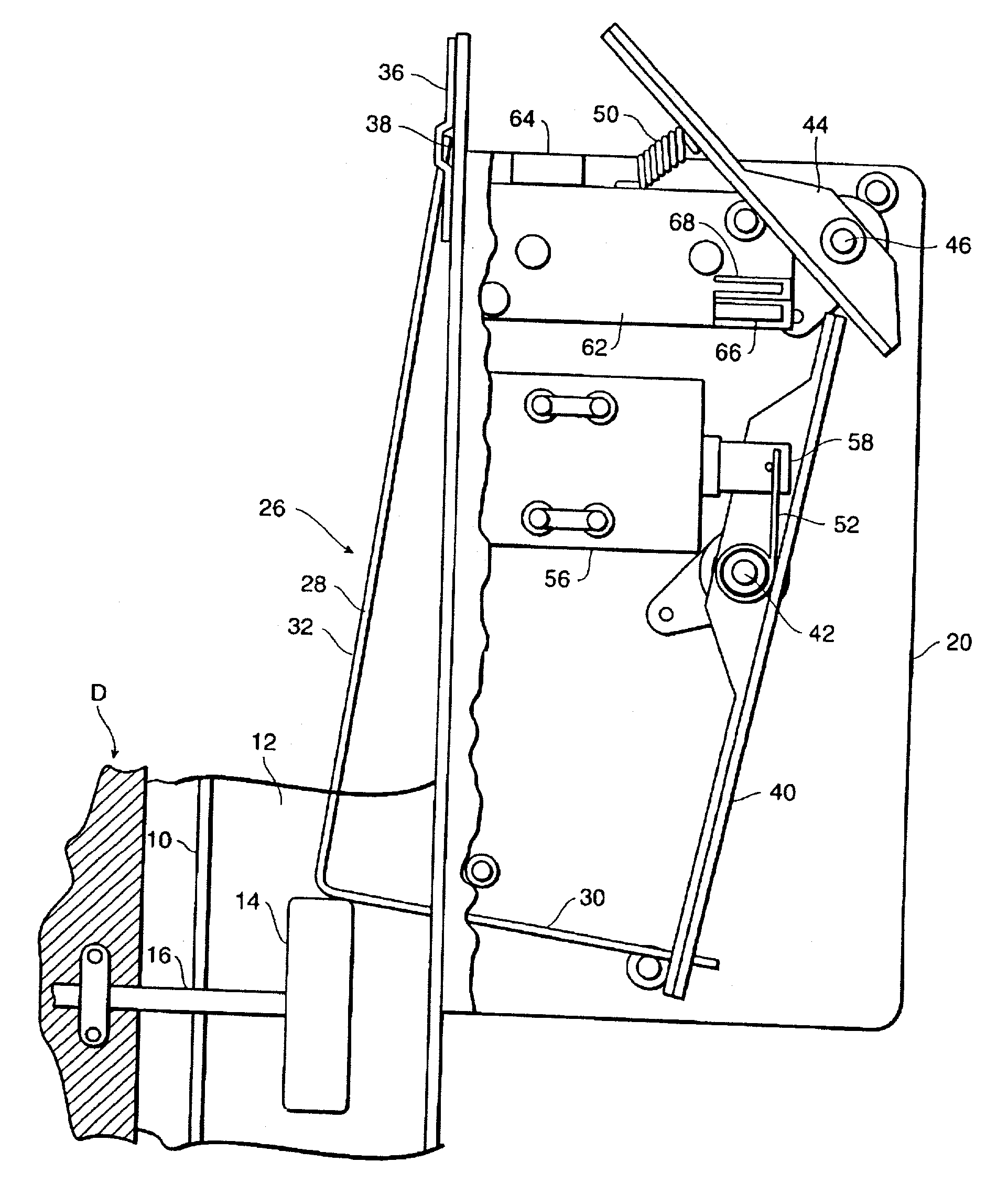
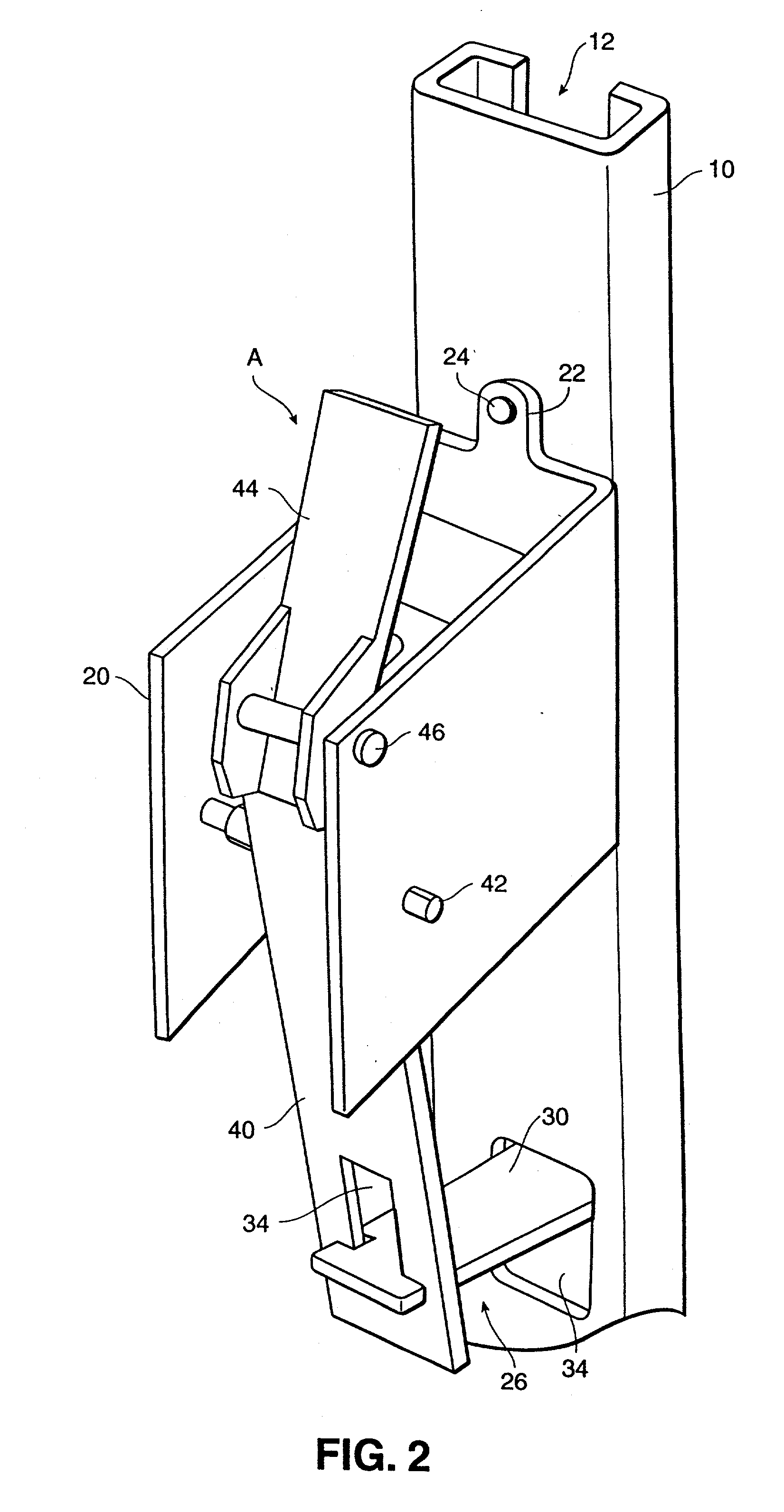
[0033] Referring now in more detail and by reference characters to the drawings, FIGS. 2-5 illustrates a door locking mechanism A of the present invention used in conjunction with an overhead door D as shown in FIGS. 4 and 5. In this case, the overhead door D is schematically illustrated although it should be understood that the door D would be mounted within a suitable frame as hereinafter described.

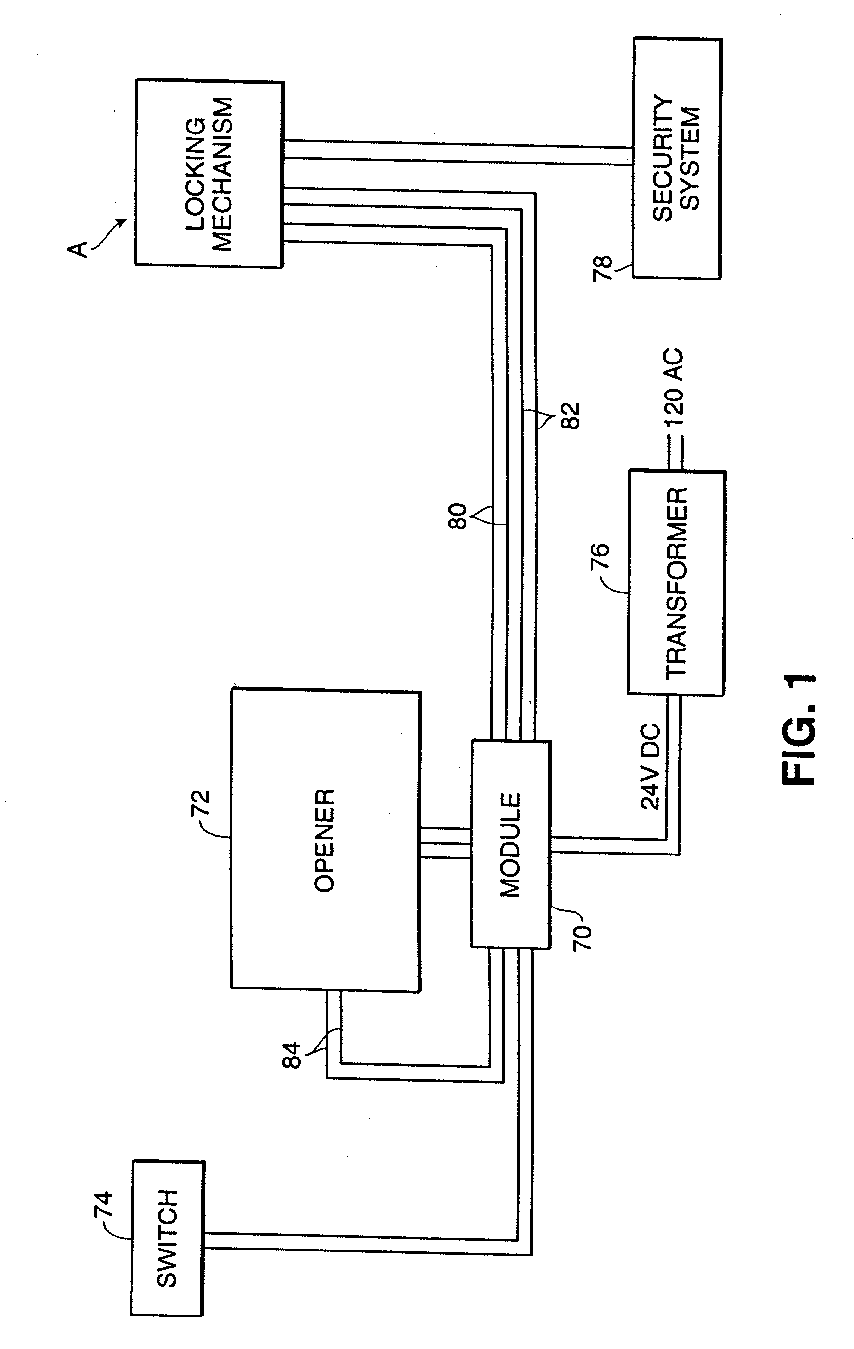
[0034] Although the door locking mechanism of the invention is shown as being used in conjunction with a conventional door operator or opener, it should be recognized that the locking assembly, per se, including the lock mechanism and the module (both as hereinafter described), could be used independently of and not in conjunction with an opener. However, in many cases, overhead doors are frequently opened and closed through the actions of a conventional remote control operated or switch activated opener and, therefore, the lock assembly of the invention is illustrated and described in ...


PUM


Abstract

A locking mechanism includes a frame having a movement obstruction arm movable into a track on which rollers of an overhead door will move. When any roller on the door abuts against the arm, it will obstruct any further opening movement of the overhead door. A camming means is associated with the movement obstruction arm to automatically shift the same to a position out of the trackway when the door is moving back to the closed position. A control module is operable with the locking mechanism and receives a signal from a locking mechanism indicative of whether or not the locking mechanism is opened or closed. The control module will thereupon provide an opening signal to an opener for the overhead door.

Description

[0001] 1. Field of the Invention[0002] This invention relates in general to certain new and useful improvements in overhead door locking mechanisms and, more particularly, to an overhead door locking mechanism operating in conjunction with a garage door opener control circuit for sensing the condition of the lock and controlling actuation of the garage door opener in response to whether or not the lock is in an opened or closed condition.[0003] 2. Brief Description of Related Art[0004] Automatic overhead garage door mechanisms are well known and used in a variety of installations as, for example, residential garage doors, warehouse doors, and the like. There are also a large number of automatic door operators for opening and closing these doors. In some cases, the doors are comprised of hingedly connected individual panels which are capable of pivoting relative to other vertically arranged panels when the door is opened. Each of the panels successively shift through an arcuate path ...

Claims


Application Information

Patent Timeline
IPC IPC(8): E05B47/00E05B65/00E05B65/08
CPCE05B47/00E05B65/0021Y10S70/11E05B2047/0094Y10S292/36E05B65/0829
Inventor SHOEMAKER, RODNEY T.
Owner SHOEMAKER RODNEY
Why Eureka
Try Eureka