
Magnetic field for small closed-drift ion source

a closed-drift ion source and magnetic field technology, applied in the field of magnetic field for small closed-drift ion sources, can solve the problems of increasing the difficulty in using geometric scaling to reduce the diameter of the mean discharge region, achieving the effect of efficiently performing over a wide operating rang

Inactive Publication Date: 2002-10-10
KAUFMAN & ROBINSON
View PDF0 Cites 32 Cited by
  • Summary
  • Abstract
  • Description
  • Claims
  • Application Information

AI Technical Summary

Benefits of technology

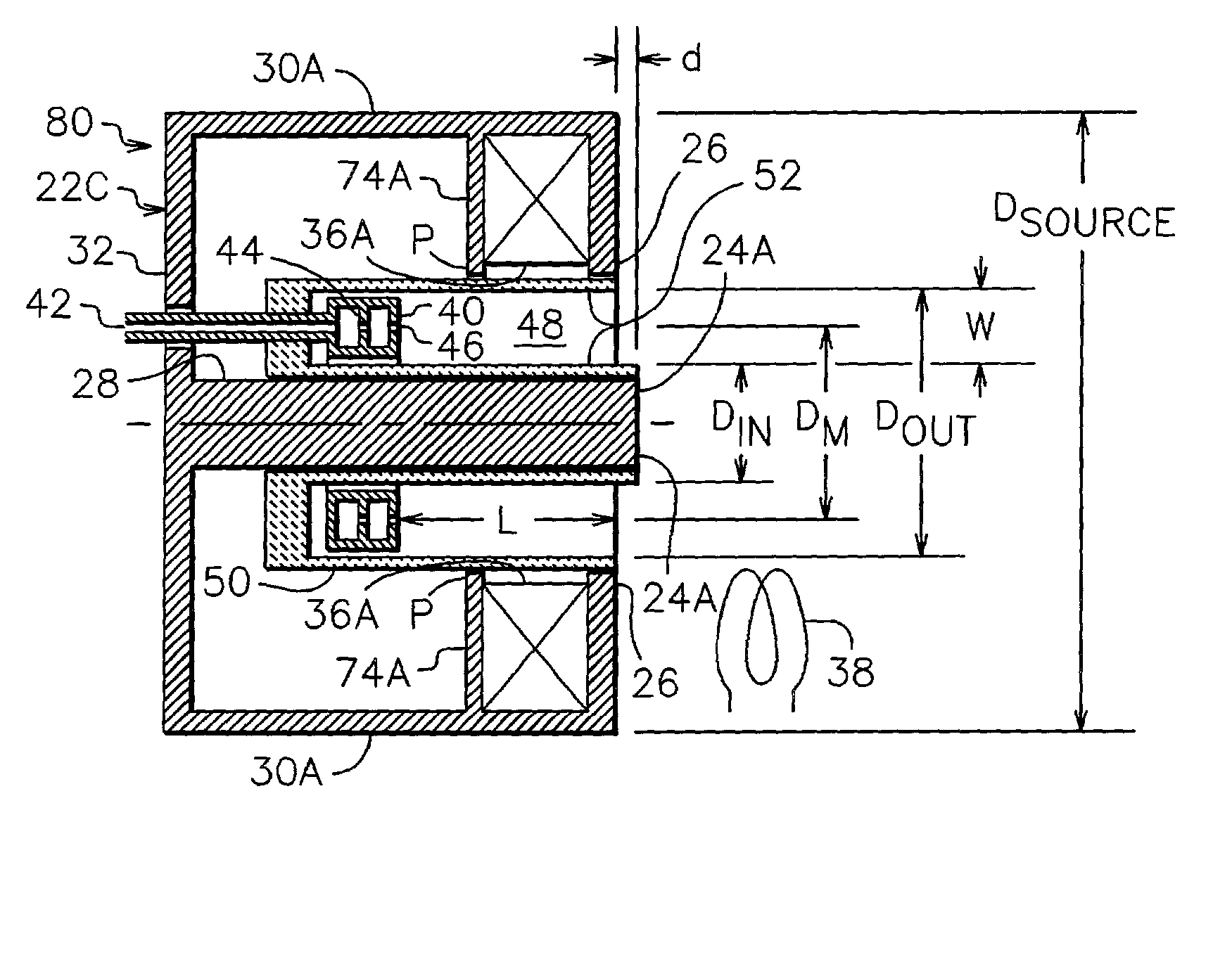
[0012] Another overall general object of the invention is to provide a magnetic field configuration that is efficient in the use of magnetic circuit elements so that it is suitable for a larger closed-drift ion source that is of the magnetic-layer or SPT type and is compact, efficient, and economical in the use of magnetically permeable material for the ion beam energy and current generated.
[0014] Another specific object of the present invention is to minimize the magnetic flux passing through the inner path of the magnetic circuit that does not directly contribute to the ionization and acceleration process, thereby reducing the flux density in that element of the magnetic circuit.
[0015] A more general object of the present invention is to minimize the gas flow required for operation by making a closed-drift ion source that has a discharge region with a small mean diameter.

Problems solved by technology

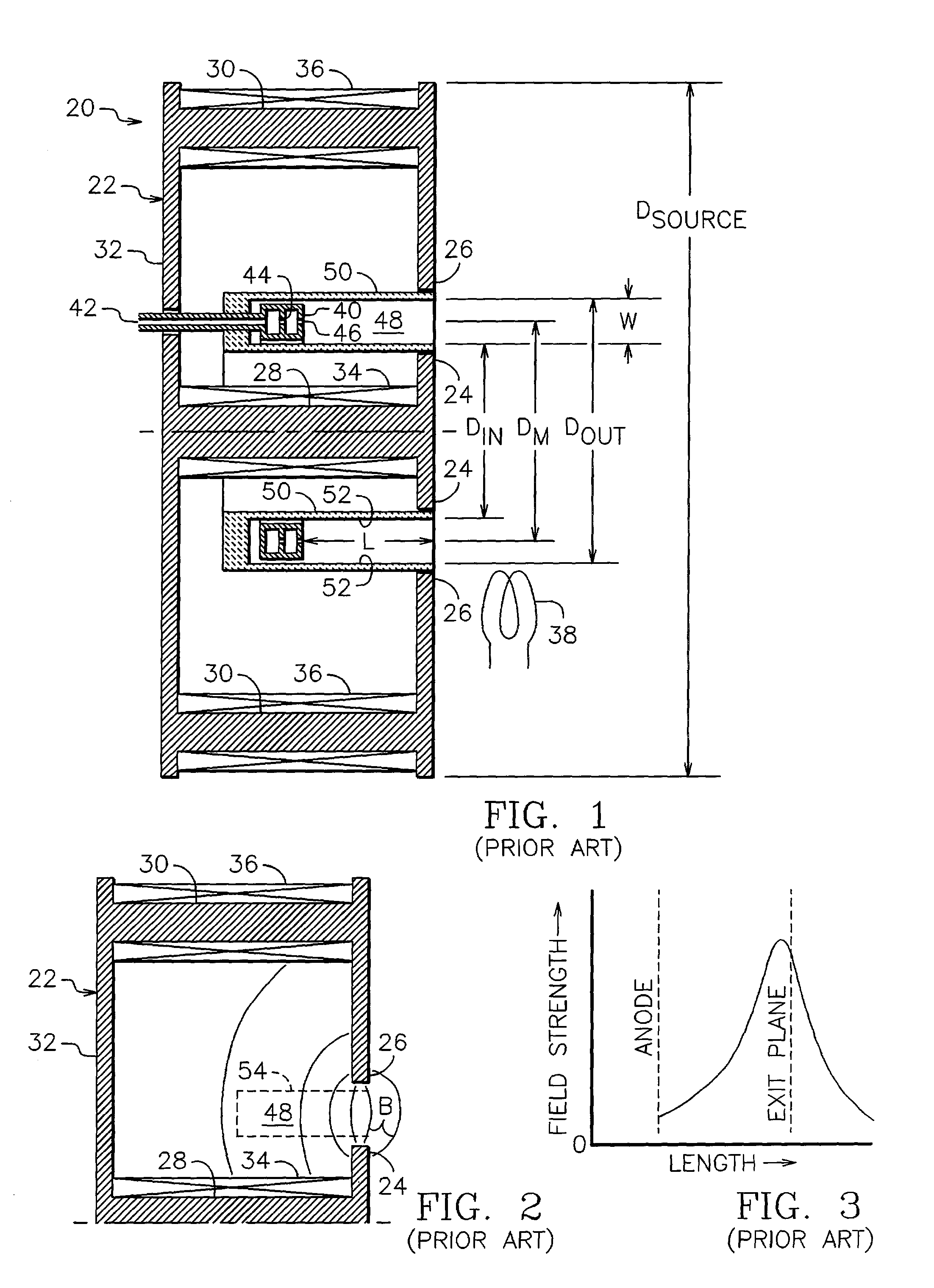
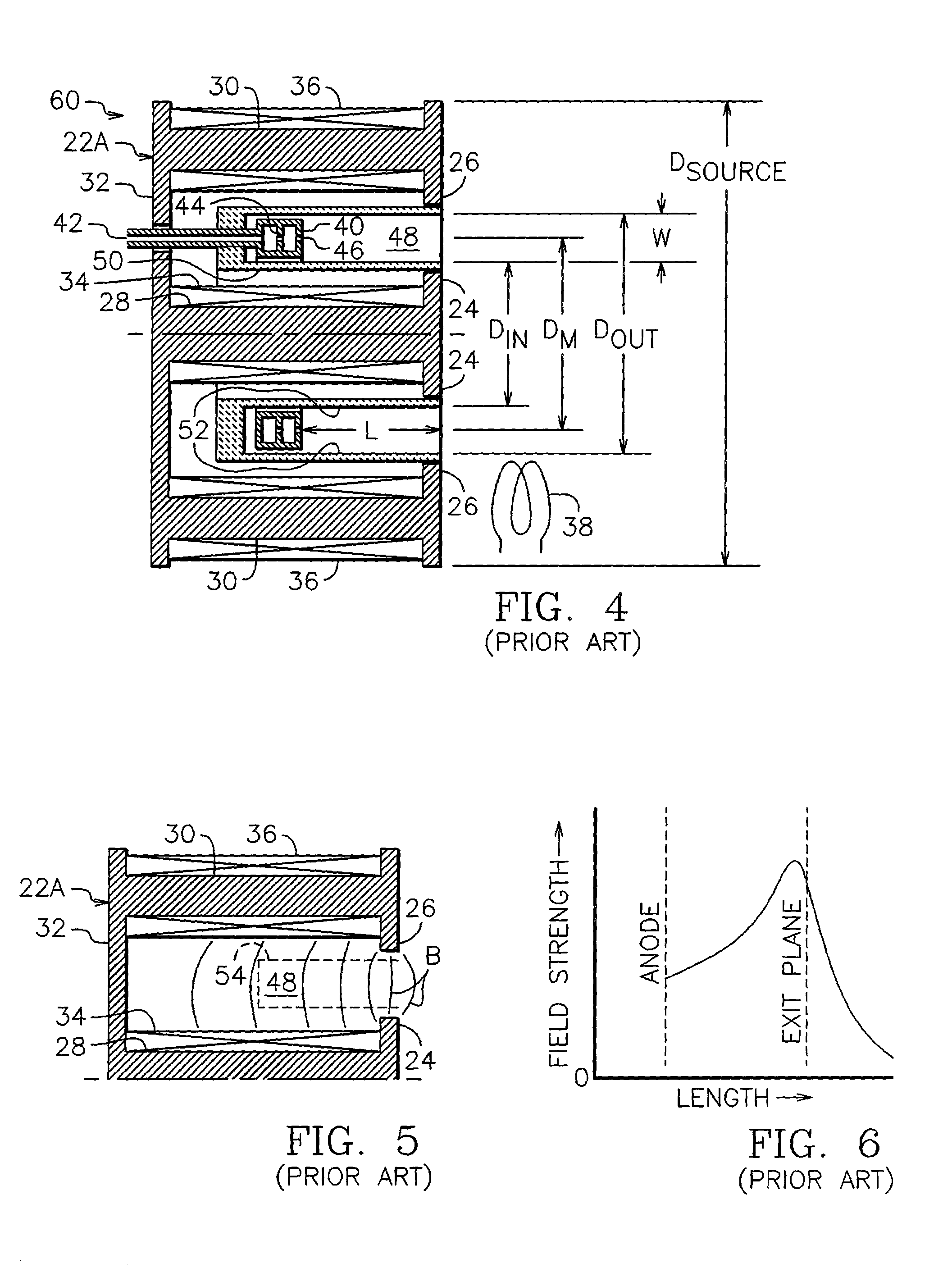
In summary, obtaining a smaller, more compact ion source by simply reducing the outer radial dimensions of a configuration similar to that of ion source 20 is not an effective approach to obtain a compact, small ion source.
However, the magnetic flux between the inner shield and the inner path of the magnetic circuit increases the flux density in the critical inner path, thus increases the difficulty in using geometric scaling to reduce the mean discharge region diameter.

Method used


Image

  • Magnetic field for small closed-drift ion source
  • Magnetic field for small closed-drift ion source
  • Magnetic field for small closed-drift ion source

Examples


specific example

[0088] Referring to FIG. 15, there is shown an approximately axisymmetric closed-drift ion source constructed in accordance with an embodiment of the present invention and generally similar to that embodiment shown in FIG. 10. Ion source 110 includes a modified magnetic circuit 22F, which is comprised of magnetically permeable inner pole piece 24A, magnetically permeable outer pole piece 26, magnetically permeable inner path 28, eight magnetically permeable outer paths 30C, magnetically permeable back plate 32, magnetically permeable magnetic shield 74C, and magnetically energizing coil 36A, all of which serve, when coil 36A is energized by an appropriate source of electrical power, to generate a magnetic field between the inner and outer pole pieces. The length of the discharge region L is shown in FIG. 15 as extending from the anode 40 to the downstream end of outer pole piece, similar to the length L shown in FIGS. 10, 13, and 14. The channel walls can extend downstream of the po...


PUM


Abstract

In one embodiment of a compact closed-drift ion source, an ionizable gas is introduced into a annular discharge region. An anode is at one end of this region and an electron-emitting cathode is near the opposite and open end. A magnetic circuit extends from an inner pole piece to an outer pole piece, with both pole pieces near the open end. The electron current in the discharge region interacts with the magnetic field therein to generate and accelerate ions out of the open end. A permeable enclosure surrounds the anode end of the discharge region. Adjacent elements of the permeable enclosure, the inner pole piece, and any intermediate permeable elements are in close proximity, one to the next. A magnetizing means is located only between the outer pole piece and the permeable enclosure.

Description

[0001] This application is based upon, and claims the benefit of, our Provisional Application No. 60 / 271,042, filed Feb. 23, 2001.[0002] This invention relates generally to ion and plasma technology, and more particularly it pertains to plasma and ion sources with closed electron drift.[0003] This invention can be used in industrial applications such as sputter etching, sputter deposition, and property enhancement. It can also find application in electric space propulsion.[0004] The acceleration of ions to form energetic beams of such ions has been accomplished both electrostatically and electromagnetically. The present invention pertains to sources that utilize electromagnetic acceleration. Such sources have in general been called electromagnetic or gridless ion sources. Because the ion beams are typically dense enough to require the presence of electrons to avoid the disruptive mutual repulsion of the positively charged ions, the ion beams are also neutralized plasmas and these io...

Claims


Application Information

Patent Timeline
Patent Type & Authority Applications(United States)
IPC IPC(8): F03H1/00
CPCH01J27/143
Inventor BUGROVA, ANTONINA IVANOVNADESIATSKOV, ALEKSEI VASILIEVICHMOROZOV, ALEKSEI IVANOVICHKHARCHEVNIKOV, VADIM KONSTANTINOVICHKAUFMAN, HAROLD R.ZHURIN, VIACHESLAV V.
Owner KAUFMAN & ROBINSON
Learn More