Integrated filter housing with associated cleaning system and method

Inactive Publication Date: 2002-09-19
ALLEGHENY BRADFORD CORP
View PDF31 Cites 23 Cited by
  • Summary
  • Abstract
  • Description
  • Claims
  • Application Information

AI Technical Summary

Benefits of technology

[0008] The present invention relates generally to filter housings and, more particularly, relates to an integrated multi-round filter housing with associated systems and methods for cleaning the filter housing using Clean-in-Place (CIP) technology. The present invention generally includes an integrated filter housing with a one-piece tooled base assembly to decrease the number of elements to be cleaned, the amount of wasted product, cleaning time, and surface area for contaminants. The filter housing is preferably adapted to use CIP cleaning technology for effective, safe and efficient cleaning of the interior portions of the filter housing.
[0009] The filter housing preferably includes an integrated base that is machined or tooled from a single piece of material. The integrated base preferably includes a plurality of machined bores adapted to accept longitudinal filter cartridges inserted therein. The base plate preferably contains a plurality of sloped bores running from the bottom of each filter cartridge bore and extending downwards and inwards to a main central outlet manifold. The sloped nature of the bores substantially reduces or virtually eliminates the amount of wasted product and increases both the efficiency and efficacy of the cleaning process.
[0010] The integrated cartridge plate may also include a recessed upper face. The upper face preferably recesses slightly downward from the outer edge of the plate to the outlet manifold (e.g., a frustoconical indentation). Again, this slight slope may reduce the amount of wasted product when compared to prior art filter housings with flat, removable cartridge plates. There may also be a channel in the upper face of the integrated base assembly that extends from the recessed portion of the face out into the top of the inlet manifold bore. When unfiltered product is drained from the dome after a product cycle, this channel preferably allows the unfiltered product to flow back into the inlet manifold for use in a future production cycle.

Problems solved by technology

This prior art design suffers from a variety of potential and actual problems.
The prior art design contains an unacceptable number of constituent elements included in the filter housing.
Many of these elements must be removed and cleaned separately after every production run, and the junctions or joints between each of these elements create areas that may include tiny crevices and cracks which may promote bacterial growth.
Also, certain pooled product may be toxic or otherwise harmful which may endanger the safety of an operator during filter housing assembly and disassembly.
Finally, the orientation of the various elements of the prior art filter housings limit the ability to use an automated cleaning system, such as Clean-In-Place (CIP) technology.
Manual cleaning increases the time between production cycles, requires valuable manpower, and reduces the overall efficiency of the filtering system.

Method used


Image

  • Integrated filter housing with associated cleaning system and method
  • Integrated filter housing with associated cleaning system and method
  • Integrated filter housing with associated cleaning system and method

Examples


Embodiment Construction

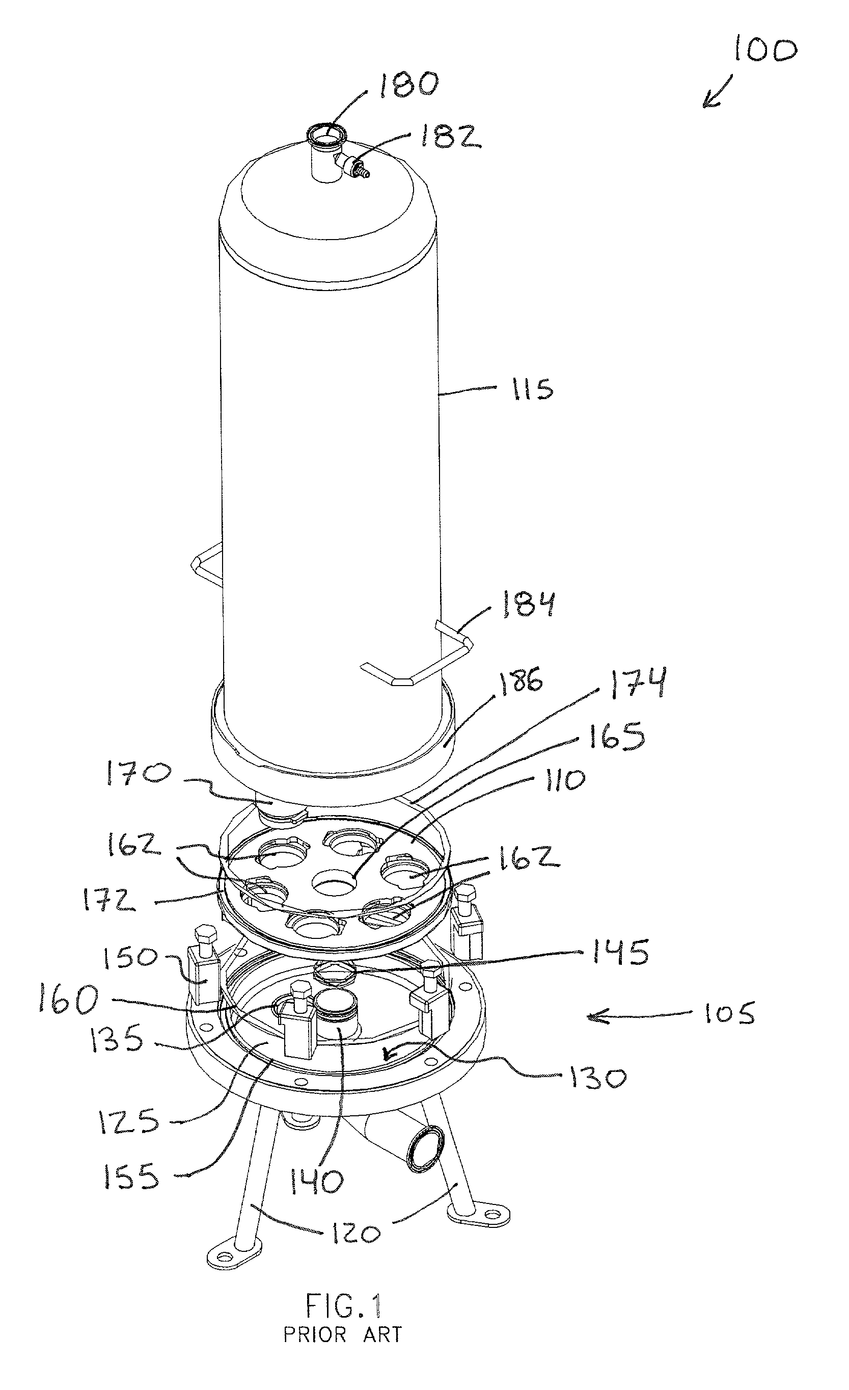
[0021] FIG. 1 depicts a typical prior art filter housing 100 including a multi-stage base assembly 105, removable cartridge plate 110 and removable dome 115.

[0022] The base assembly 105 of the prior art filter housing 100 shown is supported by three legs 120 but can be fixed in a production line in a variety of standard configurations. A collection chamber 125 is recessed within the base assembly 105 towards the bottom of the filter housing 100. The collection chamber 125 is generally annular with a flat lower face 130 which includes an outlet manifold 135 to allow filtered product to exit the filter housing 100. An inlet manifold 140, which is used to introduce an unfiltered product into the filter housing 100, extends generally upward from the center of the lower face 130 of the annular collection chamber 125. The inlet manifold 140 extends upwards towards the top of the filter housing 100 and includes one or more O-ring sealing members 145 to seal the inlet manifold 140 to the re...


PUM


Abstract

A multiround filter housing apparatus, cleaning system and method are provided. A filter housing having an integrated base that includes an integral cartridge plate, a plurality of cartridge filter bores, an inlet manifold and an outlet manifold is presented. The upper face of the integral cartridge plate is recessed to facilitate drainage of product and cleaning media. The lower portions of the cartridge filter bores are connected to the outlet port by additional sloped bores, thereby eliminating the need for a collection chamber. A spray device assembly is provided to facilitate a complete "Clean-in-Place" system in conjunction with the filter housing of the present invention.

Description

FIELD OF THE INVENTION[0001] The present invention relates generally to filter housings and, more particularly, relates to an integrated multi-round filter housing with associated systems and methods for cleaning the filter housing using Clean-in-Place (CIP) technology.BACKGROUND[0002] Filter housings are widely used in a variety of applications in the pharmaceutical, food, fine chemical and water purity industries to filter or purify fluids. Processing pressures may typically range from less than 10 p.s.i. to approximately 1000 p.s.i., depending on the specific product being filtered.[0003] Traditionally, a filter housing includes a base assembly with a deep collection chamber, a cartridge plate with a plurality of longitudinal filter cartridges attached thereto, and a dome which fits over the top of the entire filter housing (see generally, FIG. 1). These elements are typically sealed against each other using a plurality of O-rings or other gasket-type sealing devices. A plurality...

Claims


Application Information

Patent Timeline
IPC IPC(8): B01D35/16
CPCB01D35/16B01D2201/0438B01D2201/4046
Inventor MCCUNE, DANIEL P.SUTHERLAND, MICHAEL A. JR.HARVEY, THOMAS S.
Owner ALLEGHENY BRADFORD CORP
Why Eureka
Try Eureka