
Hair clipper with rotating blade assembly

a technology of rotating blades and clippers, which is applied in the direction of metal working devices, etc., can solve the problems of multiple devices being duplicated and expensive, the device with interchangeable blade assemblies has too many parts that can be easily lost, and the wide blade assemblies are too cumbersome and un-usable in areas

Inactive Publication Date: 2002-07-18
CONAIR CIP INC
View PDF0 Cites 36 Cited by
  • Summary
  • Abstract
  • Description
  • Claims
  • Application Information

AI Technical Summary

Benefits of technology

[0012] It is an object of the present invention to provide a clipper that presents both wide and narrow blade assemblies to the user.
[0014] It is another object of the present invention to provide a clipper with a blade assembly that rotates about an axis substantially normal to the cutting plane defined by the blade assembly so as to present to the user one of several different cutting edges.
[0014] It is another object of the present invention to provide a clipper with a blade assembly that rotates about an axis substantially normal to the cutting plane defined by the blade assembly so as to present to the user one of several different cutting edges.
[0015] It is a further object of the present invention to provide a rotatable clipper having a single cutting blade.

Problems solved by technology

However, wide blade assemblies prove to be too cumbersome and un-useable in areas such as the nose, ears, and the like.
Multiple devices are duplicative and expensive.
A single device with interchangeable blade assemblies has too many parts that can be easily lost.
Thus, the use of wide and narrow blades in the same blade assembly is not provided.
However, the ability to rotate the blade assembly about an axis substantially normal to the cutting plane defined by the blade assembly is not provided.
Moreover, the use of wide and narrow blades in the same blade assembly is not provided.
However, the ability to rotate the blade assembly about an axis substantially normal to the cutting plane defined by the blade assembly is not provided.
Moreover, the use of wide and narrow blades in the same blade assembly is not provided.
Moreover, such a simple rotatable clipper having a single cutting blade is not provided.

Method used


Image

  • Hair clipper with rotating blade assembly
  • Hair clipper with rotating blade assembly
  • Hair clipper with rotating blade assembly

Examples


Embodiment Construction

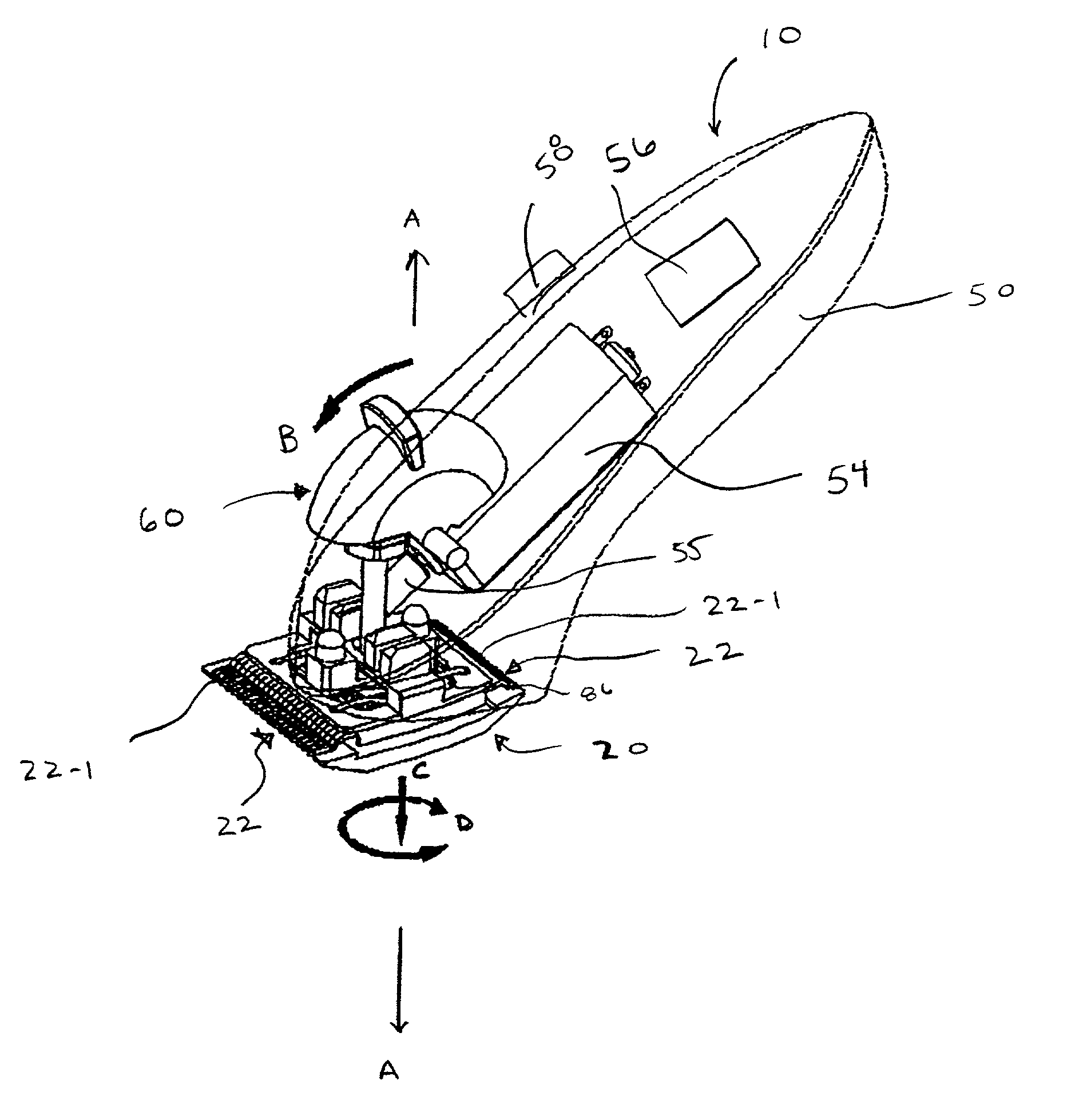
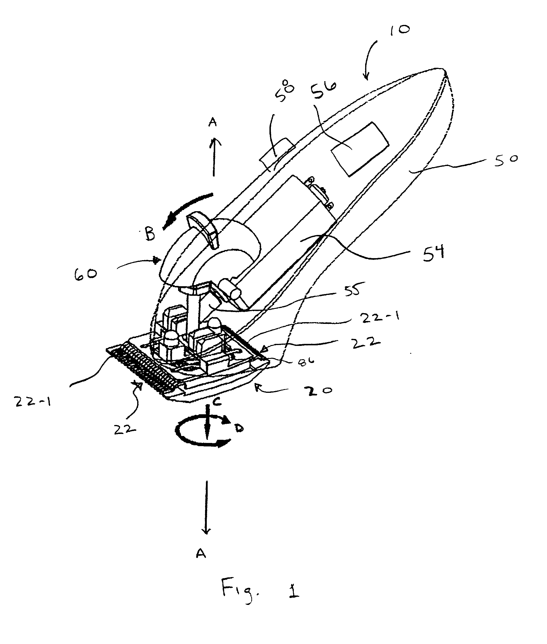
[0020] Referring to the figures and particularly to FIG. 1, a clipper, generally represented by reference numeral 10, is shown. Clipper 10 includes a blade assembly 20 and a housing 50. Clipper 10 is adapted to rotate blade assembly 20 about an axis, designated axis A. Axis A is substantially normal or perpendicular (hereinafter normal) to the cutting plane defined by blade assembly 50. Blade assembly 20 includes more than one cutting edge 22 that define the cutting plane of the blade assembly. Thus, clipper 10 is adapted to present more than one cutting edge 22 to the user.

[0021] In the embodiment of FIG. 1, blade assembly 20 has a wide cutting edge 22-1 and a narrow cutting edge 22-2. Thus, clipper 10 is adapted to present the user with the ability to convert the clipper from one with a wide cutting edge 22-1 for certain uses to one with a narrow cutting edge 22-2 for other uses.

[0022] It should be understood that the present invention is described by way of example. Thus, it shou...


PUM


Abstract

There is provided a hair clipper with a housing having a control for selectively connecting a motor positioned in the housing to an energy source. The hair clipper also having a rotating blade assembly with one or more cutting edges and a switch mechanism operatively connected to said blade assembly. The hair clipper allows the blade assembly to be efficiently and effectively adjusted to conveniently provide a user with several different hair cutting options.

Description

[0001] 1. Field of the Invention[0002] The present invention relates to hair clippers or trimmers. More particularly, the present invention relates to a hair clipper having a rotating clipper blade assembly. The clipper blade assembly of the present invention rotates about an axis substantially normal to the cutting plane defined by the blade assembly.[0003] 2. Description of the Prior Art[0004] Electric hair clippers having a clipper blade assembly including a stationary blade and a reciprocating blade are known in the art. The stationary blade and the reciprocating blade each have a plurality of teeth along the leading edge of the blades. The clipper blade assembly is mounted to the clipper handle such that the teeth of the stationary blade are substantially parallel to the teeth of the reciprocating blade. In this manner, reciprocating the reciprocating blade with respect to the stationary blade trims hair positioned between the teeth.[0005] The width of the blade assembly dictat...

Claims


Application Information

Patent Timeline
IPC IPC(8): B26B19/38B26B19/06
CPCB26B19/063B26B19/10
Inventor FUNG, KAM FAI
Owner CONAIR CIP INC
Learn More