
Adapter for ophthalmologic equipment

a technology for adapters and ophthalmologic equipment, which is applied in the field of adapters for ophthalmologic equipment, can solve the problems of complex construction, high production cost, and inability to exchange the same for different slit lamp microscopes,

Inactive Publication Date: 2002-03-07
CARL ZEISS JENA GMBH
View PDF0 Cites 3 Cited by
  • Summary
  • Abstract
  • Description
  • Claims
  • Application Information

AI Technical Summary

Benefits of technology

[0011] It is thus advantageous if at least the one fastening means is or the more than one fastening means are adjustable along one axis relative to the base body.
[0015] It is also advantageous if a positively locking connection is provided between base body and laser link by means of which relative movement of the two parts connected with each other is avoided.
[0016] It is furthermore advantageous if the one or more fastening means arranged on the base body of the adapter with which the adapter can be coupled to the housing of the slit lamp microscope can be adjusted or positionally altered with at least one degree of freedom to attain a precisely defined mutual position of the connected parts.

Problems solved by technology

The disadvantage of this device is the fact that attaching the laser link and exchanging the same is not possible for different slit lamp microscopes, since a separate link must be provided for each different combination of equipment (link-slit lamp) because of the arm that is permanently attached to the link.
The transition piece comprises means for setting and adjusting the mutual positions of the respective parts and is therefore of a complicated construction and expensive to produce.

Method used


Image

  • Adapter for ophthalmologic equipment
  • Adapter for ophthalmologic equipment
  • Adapter for ophthalmologic equipment

Examples


Embodiment Construction

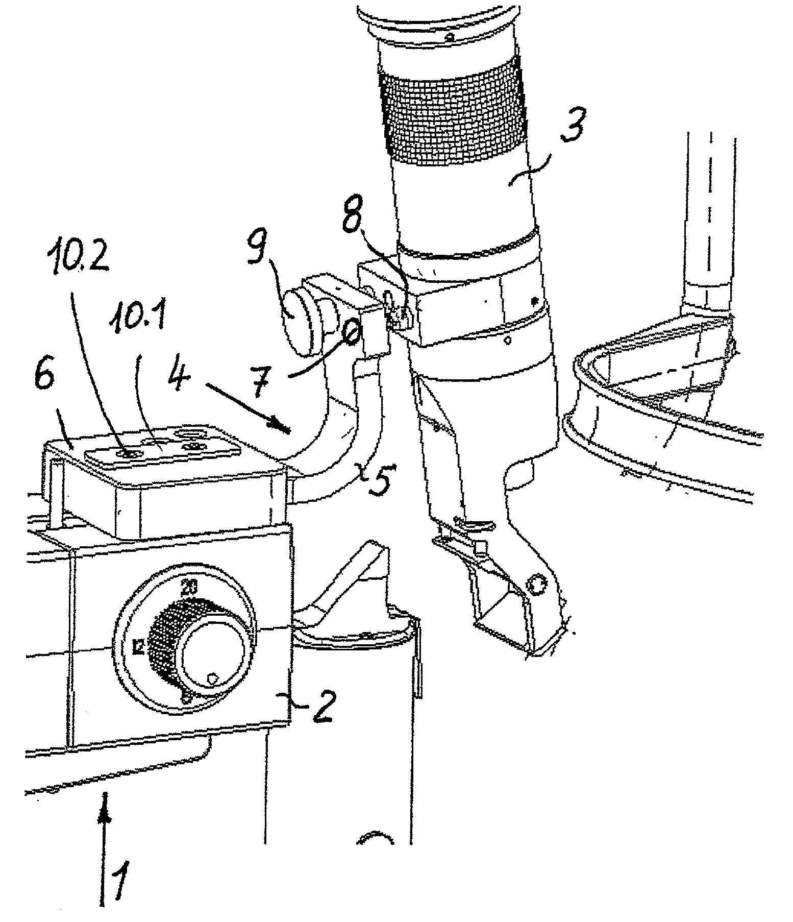
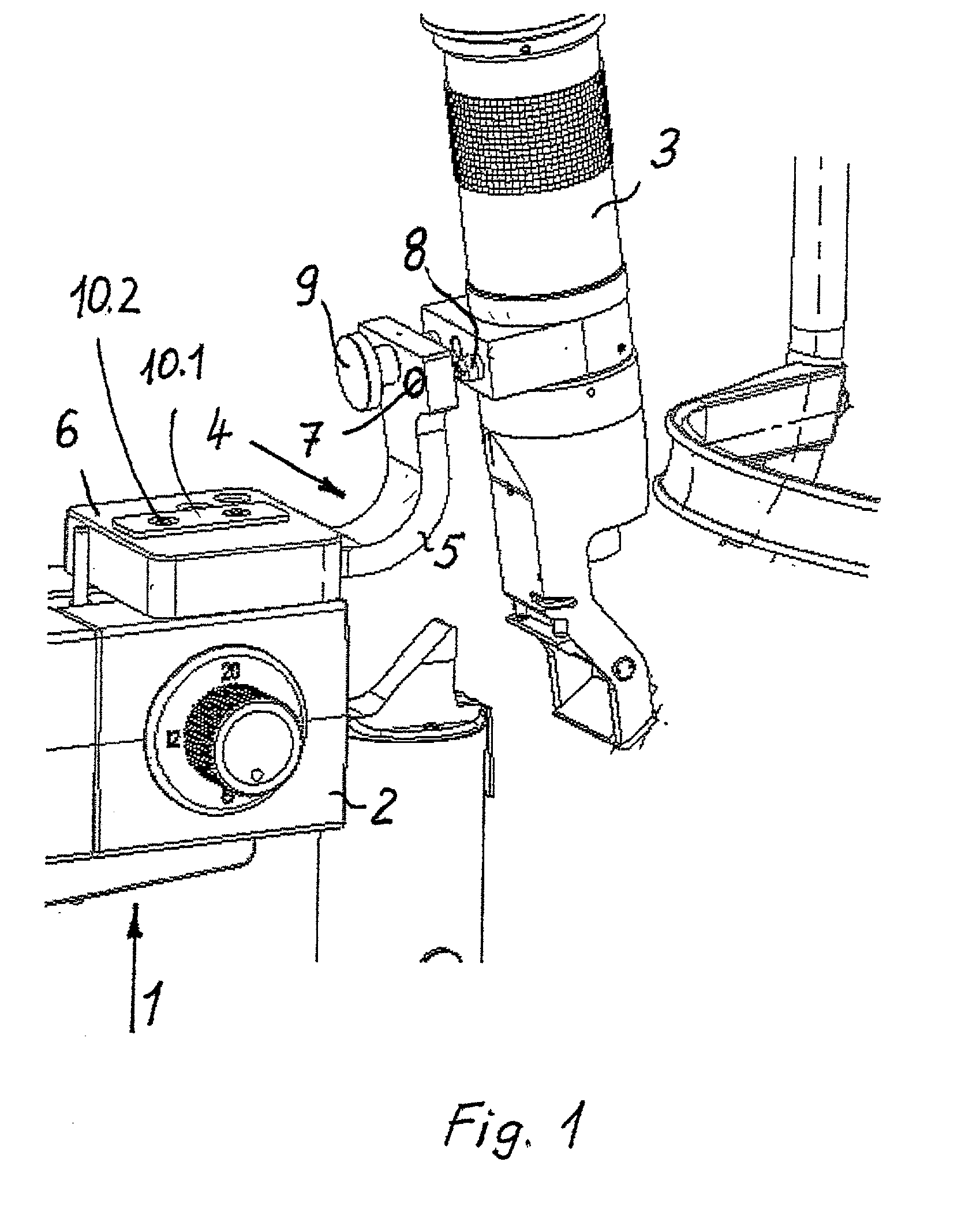
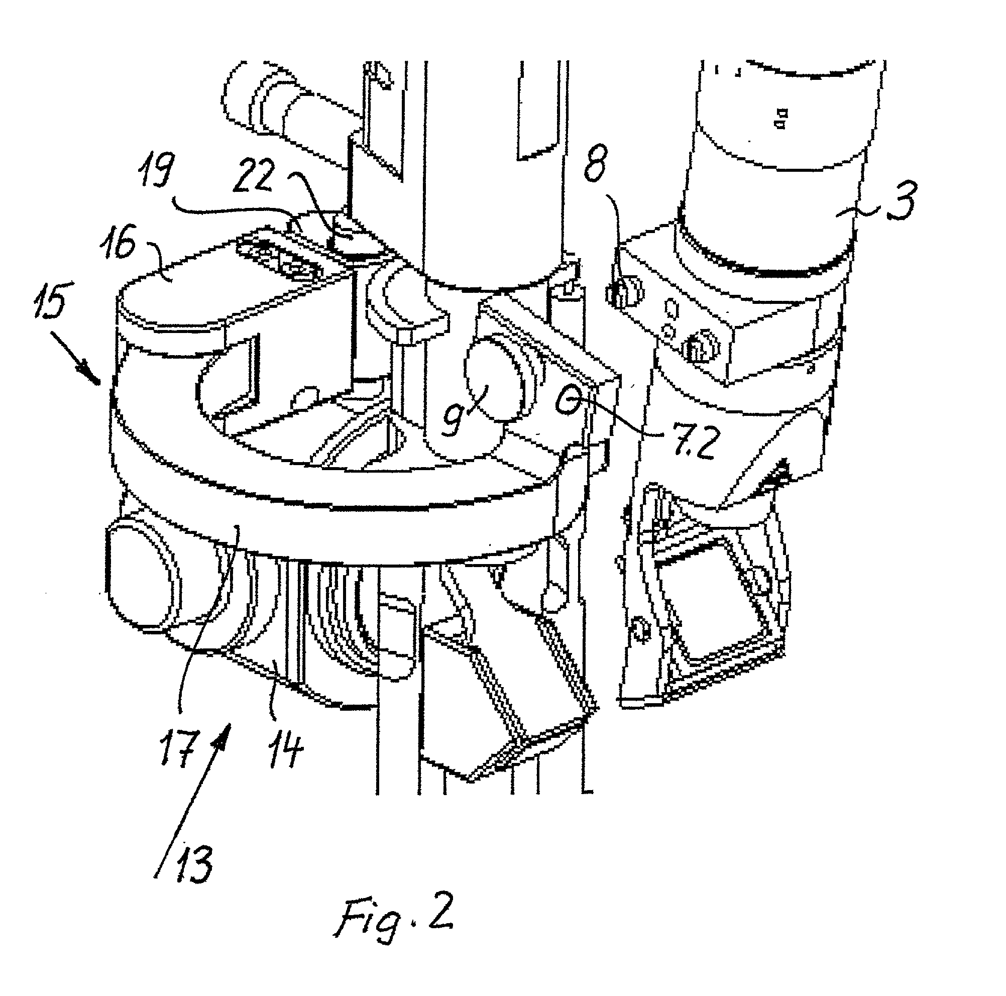
[0026] In FIG. 1, an slit lamp microscope 1 with a housing 2 and a laser link 3 is illustrated in a perspective drawing wherein the connecting part between the laser link 3 and the housing 2 is represented as an adapter 4. The adapter 4 includes a base body 5 on which a fastening means 6 is provided on the end facing the housing 2 of the slit lamp microscope 1 by means of which it can be connected with the housing 2 in a manner that is positionally aligned, releasable and has no play. On the end of the base body 5 that faces the laser link 3, first means of coupling 7 or coupling elements as well as position securing elements 9 are provided for coupling the laser link 3 to the adapter 4 in a manner that is positionally aligned, releasable and has no play, these first coupling elements 7 being in a rigid, positively and frictionally locking operative connection with matching complementary second coupling means 8 arranged on the laser link 3. The position securing elements 9, represen...


PUM


Abstract

An adapter is disclosed for ophthalmologic equipment for the defined connection and positioning of a laser link on the housing of different slit lamp microscopes . The adapter comprises a base body, on the one end of which a fastening device is provided for fastening it to the housing of a slit lamp microscope in a manner that is positionally aligned, releasable and has no play, and on the other end of which contiguous to the laser link a first device of coupling or coupling elements and / or position securing elements are provided for coupling the laser link to the housing of a slit lamp microscope in a manner that is positionally aligned, releasable and has no play. This first coupling device can be engaged in a rigid operative connection with a matching complementary second coupling device of the laser link.

Description

[0001] a) Field of the Invention[0002] The invention is directed to an adapter for ophthalmologic equipment, in particular for equipment for photodynamic therapy (PDT) or for laser coagulation in the eye, the adapter being provided for the defined fastening and positioning of a laser link on slit lamp microscopes.[0003] For such equipment, the laser link is used for introducing the radiation usually supplied via light conductors from distant laser radiation sources into the eye of the patient and for directing or splitting off light for the observation of the interior of the eye into the observation ray path of the slit lamp microscope.[0004] b) Description of the Related Art[0005] From U.S. Pat. No. 5,954,711, the provision of a fixed arm for a laser coagulation device (laser link) is known, wherein this fixed arm has means for connecting this device in a precisely defined relative position to the housing of the slit lamp microscope. This laser link is used for introducing laser ra...

Claims


Application Information

Patent Timeline
IPC IPC(8): A61B3/135A61B90/25A61B3/12A61F9/007A61F9/009
CPCA61B3/135A61F9/00821A61F9/009
Inventor LUEMKEMANN, FRANKHOFMANN, EBERHARD
Owner CARL ZEISS JENA GMBH
Learn More