Sculpted Carburetor Chamber

a carburetor chamber and sculpted technology, applied in the field of sculpted carburetor chambers, can solve the problems of laborious and time-consuming tasks, and achieve the effect of improving the flow of carbureted air and enhancing engine performan

Inactive Publication Date: 2001-10-04
KAHLHAMER BRUCE ROLAND
View PDF0 Cites 3 Cited by
  • Summary
  • Abstract
  • Description
  • Claims
  • Application Information

AI Technical Summary

Benefits of technology

0031] The central disposition of the auxiliary fuel jet aperture emission site (70) provides an improved carburetion mix of fuel and air observed under testing conditions to eliminate fuel droplet formation therein. The site (10) provides that fuel emission from a fuel jet (850) auxiliary to that issuing from the needling jet (800) be emitted at a point much nearer the engine's combustion chamber than in prior art models, thereby delivering an improved flow of carbureted air thereto.
0032] These features, working in conjunction with one another dramatically enhance engine performance for all engines in general and provide, in particular, excitement for operators of sports vehicles.

Problems solved by technology

The needle advancement and retraction means (300) simplify access to and adjustment of the position of the multiply beveled fuel flow interference needle (37) with reference to the needling fuel jet (800), an otherwise laborious and time consuming task at prior art.

Method used


Image

  • Sculpted Carburetor Chamber
  • Sculpted Carburetor Chamber
  • Sculpted Carburetor Chamber

Examples


Embodiment Construction

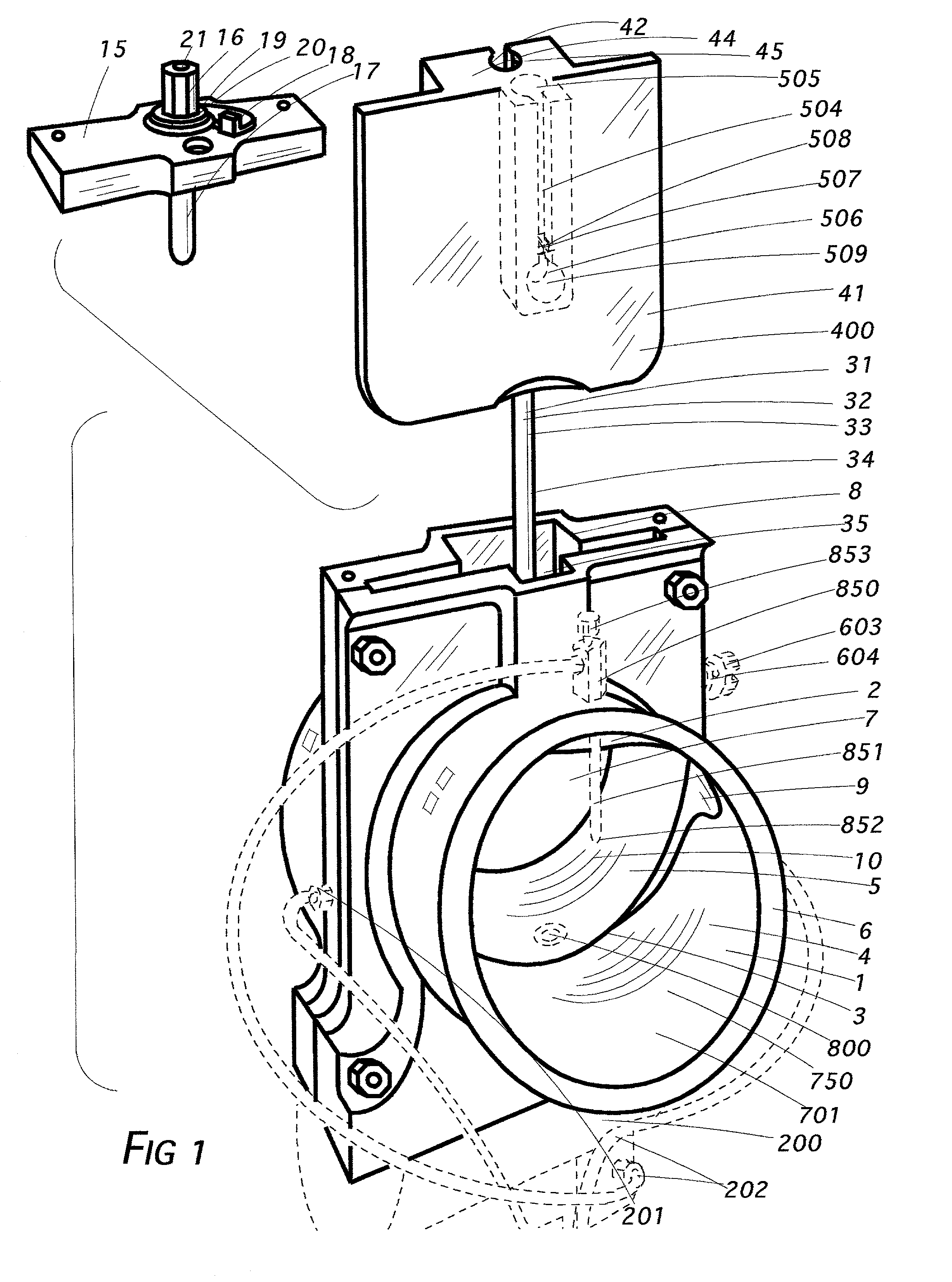
[0044] The subject of this application is a carburetor comprising performance improving features provided by innovations revealed herein which, working in conjunction with one another, achieve startling results.

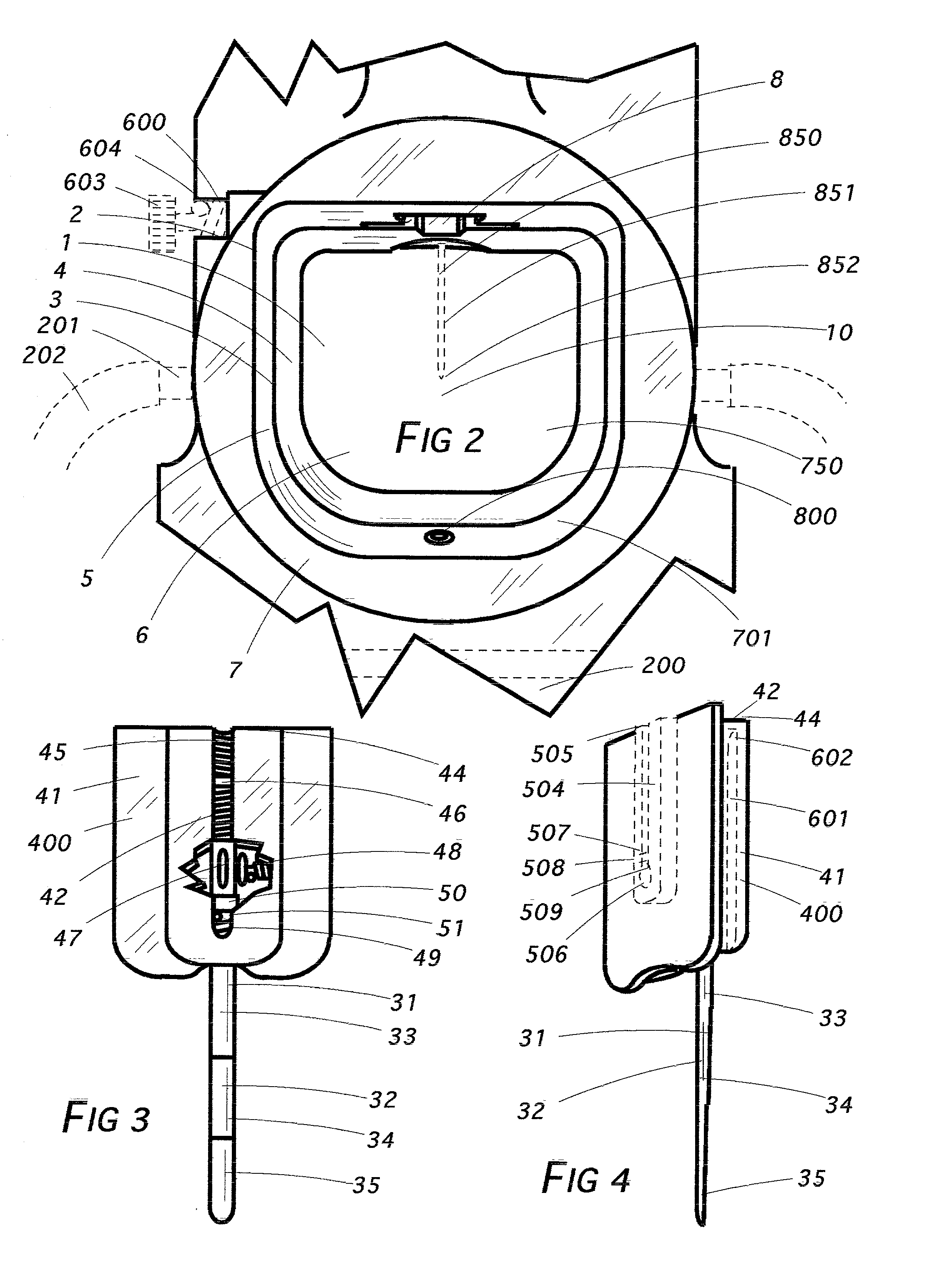
[0045] The invention features a carbureting chamber (1) which, as shown most clearly in FIG. 2, comprises D-shaped configuration (2). The meaning of that term is intended to suggest in part that the circular cross section of the chamber (700) known to prior art is truncated herein so that the cross sectional shape is like that of the letter D turned sideways with the flat portion thereof at the top.

[0046] It is already recognized, of course, that the chamber, whether of prior art or the one disclosed herein (700, 1, respectively) comprises a wall deliberately made convex (701) in emulation of the Venturi curve present in a tubular inner restriction. That curvature (701) runs essentially from the chamber's air intake end (6) most or all of the way to its opposing effluxive end...


PUM

PropertyMeasurementUnit
depthaaaaaaaaaa
areaaaaaaaaaaa
pressureaaaaaaaaaa

Abstract

A carburetor comprising four distinct features providing improved performance: A sculpted chamber comprising D-shaped configuration; a fuel flow interference needle multiply comprised with bevel zones; easily accessible needle advancement and retraction means; and a centrally disposed auxiliary fuel jet aperture emission site.

Description

[0001] This instrument, filed under 37 CFR 1.53(b) and 1.78, invoking the provisions of 35 U.S.C. 120 by reason of 35 U.S.C. 121, is a Divisional Application of presently copending application Ser. No. 09 / 394,663 entitled "Improved Performance Carburetor", filed Sep. 12, 1999.BACKGROUND OF THE INVENTION[0002] 1. Field of the Invention[0003] Combustion engine accessories[0004] 2. Description of the Prior Art[0005] Occasionally a descriptive term in this application may be shortened so as to recite only a part rather than the entirety thereof as a matter of convenience or to avoid needless redundancy. In instances in which that is done, applicant intends that the same meaning be afforded each manner of expression. Thus, the term fuel flow interference needle (31) might be used in one instance but in another, if meaning is otherwise clear from context, expression might be shortened to interference needle (31) or merely needle (31). Any of those forms is intended to convey the same mean...

Claims


Application Information

Patent Timeline
Patent Type & Authority Applications(United States)
IPC IPC(8): F02M9/06F02M19/04
CPCF02M9/06Y10S261/38F02M19/04
Inventor KAHLHAMER, BRUCE ROLAND
Owner KAHLHAMER BRUCE ROLAND
Why Eureka
Try Eureka