
Work light

a work light and light body technology, applied in the field of work lights, can solve the problems of limited illumination area of fixed work lights, heavy weight of conventional portable work lights, and difficulty in moving from place to place, so as to facilitate storage and carriage, enhance the practical use of work lights, and minimize the size of work lights

Active Publication Date: 2022-09-27
NINGBO FUTAI ELECTRIC CO LTD
View PDF5 Cites 0 Cited by
  • Summary
  • Abstract
  • Description
  • Claims
  • Application Information

AI Technical Summary

Benefits of technology

The solution provides a work light that is easily portable, adjustable, and efficient in illumination, allowing for extended illumination range and secure storage, addressing the limitations of conventional portable work lights.

Problems solved by technology

However, the major drawback of the fixed work lights is that the fixed work lights are difficult to move from places to places.
However, due to the small size of the flashlight, the flashlight can only provide a limited illumination area.
Firstly, some conventional portable work lights are too bulky to carry and store.
Secondly, some conventional portable work lights are too small with limited illumination area, such that the conventional portable work lights must be frequently moved around to illuminate different areas, which is inconvenient to use and operate.
Thirdly, the conventional portable work lights are difficult to retain the position during the usage, wherein the conventional portable work lights can only be affixed at a specific position and cannot be adjusted with respect to different working environments.
Fourthly, the illumination angle of the conventional portable work light is fixed according to the installation position thereof and is difficult to adjust.
Fifthly, the conventional portable work lights must be stored in a proper manner, wherein the conventional portable work lights could be damage when the conventional portable work lights are stored improperly.
However, the conventional fixed work lights cannot meet the above mentioned need because the conventional fixed work lights are difficult to move for illuminate specific areas under the hood and the illumination range of the conventional fixed work lights is too small.
It is a hassle for the user to frequently move the work light around to illuminate different areas.
If the size of the work light is increased to enlarge the illumination area, the larger work light is difficult to carry and store.

Method used


Image

  • Work light
  • Work light
  • Work light

Examples


second embodiment

[0180]It is worth mentioning that any type of the resilient element 133A can be used in the second embodiment, and it should not be limited in the present invention. For example, the resilient element 133A is embodied as a compression spring in this embodiment.

[0181]As shown in FIGS. 16 to 19, the plug head 131A has an interior cavity 1311A, a plug head opening 1312A and two engaging slots 1313A, wherein the plug head opening 1312A is formed at one side of the interior cavity 1311A. The two engaging slots 1313A are formed at two opposite sidewalls of the interior cavity 1311A to communicate with the interior cavity 1311A, wherein the two engaging slots 1313A are coaxially aligned with each other. The holding unit 132A is disposed in the interior cavity 1311A of the plug head 131A at a position that the two through holes 1321A are coaxially aligned with the two engaging slots 1313A of the plug head 131A respectively, wherein a diameter size of the through hole 1321A is larger than a ...

third embodiment

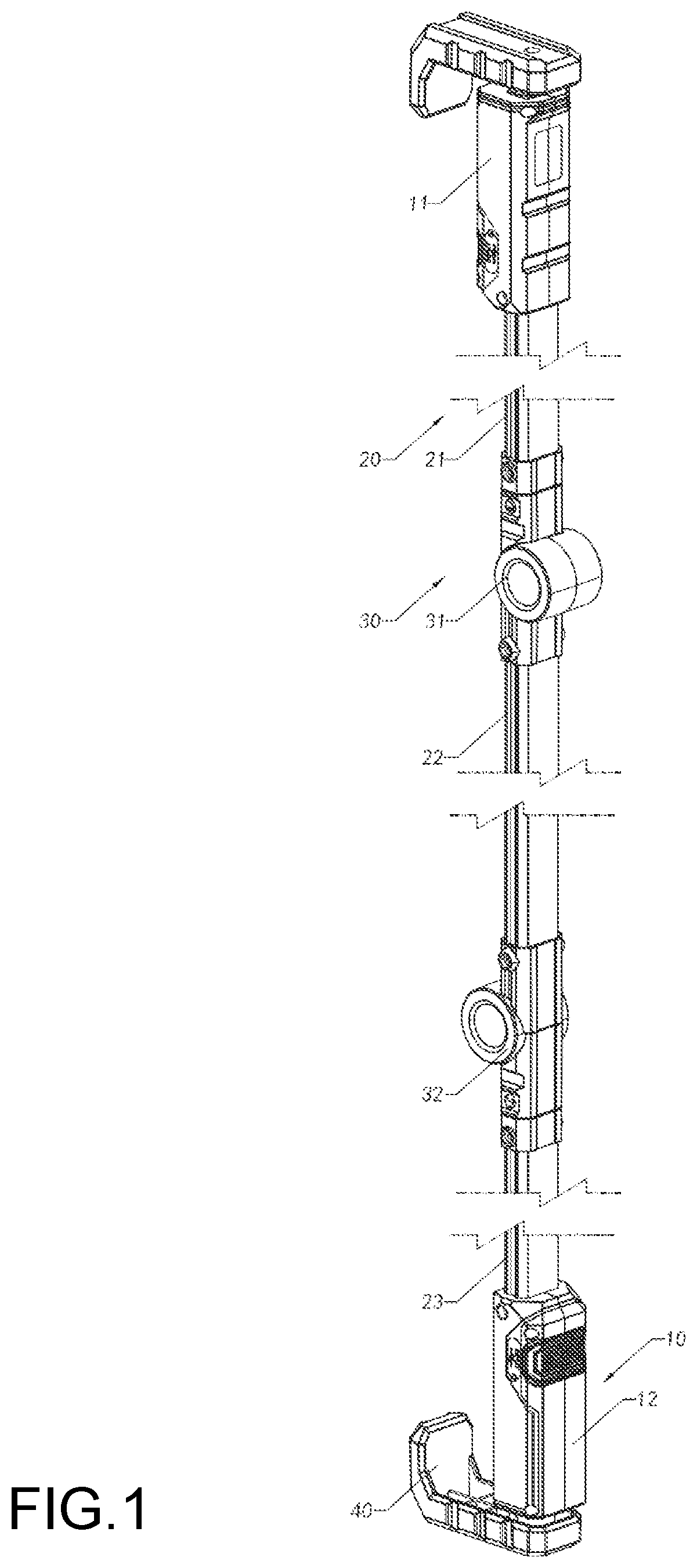
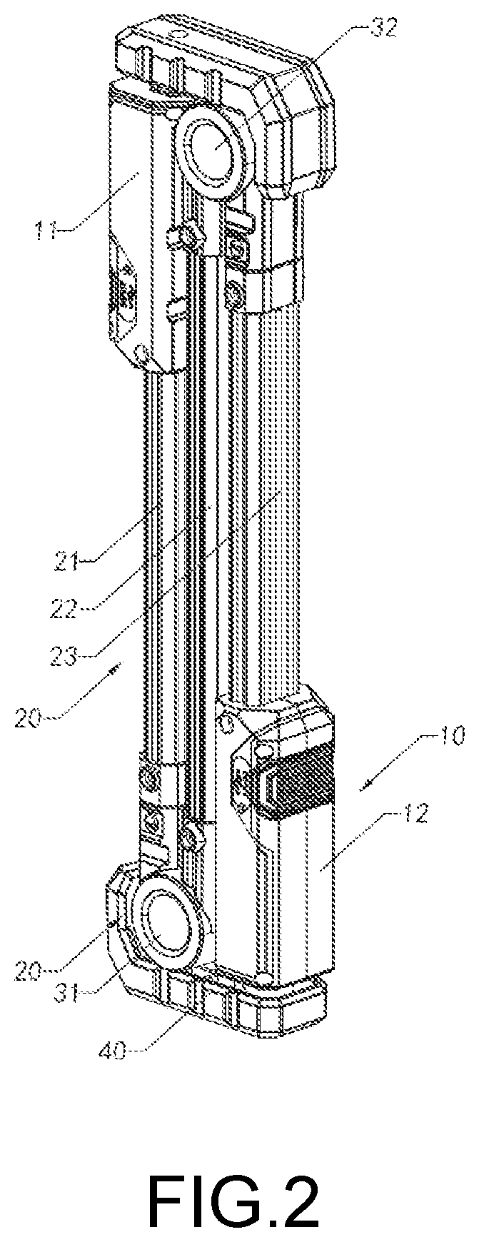
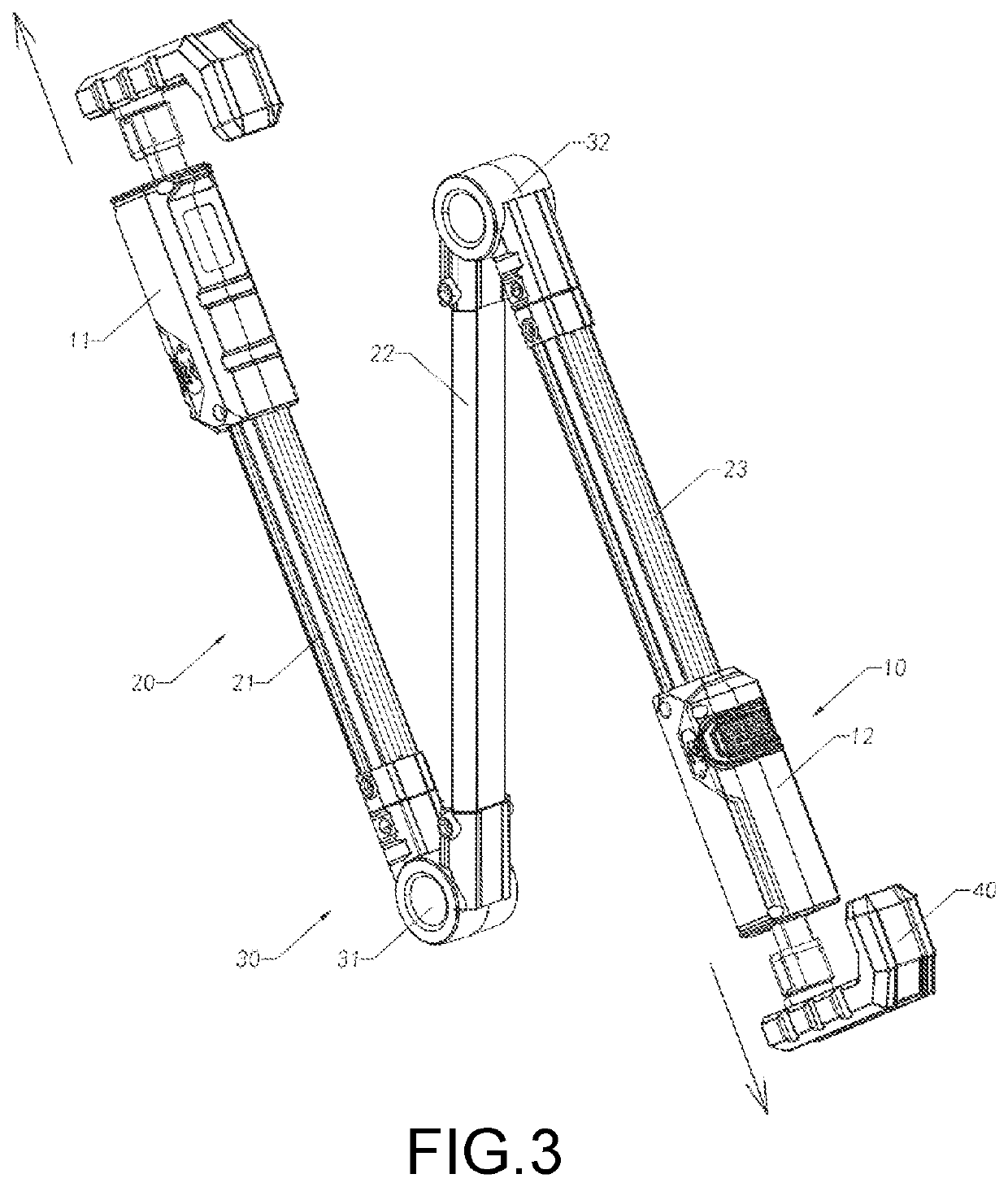
[0193]Referring to FIGS. 22 to 41 of the drawings, a work light according to the present invention is illustrated, wherein the work light comprises at least two light units A10 and at least one connection unit A20 serving as a pivot unit, wherein the connection unit A20 is coupled between the light units A10, such that the light units A10 are coupled end-to-end are adapted to be pivotally rotated via the connection unit A20 to move between a folded position and an unfolded position. In other words, the work light can be switched between the folded position and the unfolded position.

[0194]In one example, there are three light units A10 and two connection units A20, wherein the light units A10 and the connection units A20 are coupled with each other and are located alternating with each other. In other words, every two of the light units A10 are connected by one connection unit A20. It is appreciated that in another example, there are two light units A10 and one connection unit A20. L...


PUM

PropertyMeasurementUnit
pivot angleaaaaaaaaaa
rotation angleaaaaaaaaaa

Abstract

A work light includes at least one power supply unit, and at least one light unit, and at least one connection unit. The power supply unit, the light unit and the connection unit are electrically connected with each other. The light unit is detachably and pivotally coupled to the connection unit. When two or more of the light units are provided, the light units are coupled with each other in series via the connection unit. By changing the number of the light units, an overall length of the work light is selectively adjusted to adjust an illumination range of the work light according to different illumination applications.

Description

CROSS REFERENCE OF RELATED APPLICATION[0001]This is a non-provisional application that claims priority under 35 U.S.C. § 119 to Chinese application number CN 202110799526.0, filed and Jul. 15, 2021, and second Chinese application, application number CN 202011180763.0, filed Oct. 29, 2020, the entire contents of each of which are expressly incorporated herein by reference.NOTICE OF COPYRIGHT[0002]A portion of the disclosure of this patent document contains material which is subject to copyright protection. The copyright owner has no objection to any reproduction by anyone of the patent disclosure, as it appears in the United States Patent and Trademark Office patent files or records, but otherwise reserves all copyright rights whatsoever.BACKGROUND OF THE PRESENT INVENTIONField of Invention[0003]The present invention relates to a light apparatus, and more particularly to a work light and its folding method and self locking method.Description of Related Arts[0004]Work lights are consi...

Claims


Application Information

Patent Timeline
Patent Type & Authority Patents(United States)
IPC IPC(8): F21L4/02F21V21/116F21V23/06F21Y103/10
CPCF21L4/02F21V21/116F21V23/06F21Y2103/10F21L14/026F21Y2115/10F21W2131/402F21V17/007F21V21/0885B60Q7/00B60Q3/35
Inventor QIU, FUJUN
Owner NINGBO FUTAI ELECTRIC CO LTD
Learn More