USB charging apparatus

a charging apparatus and usb technology, applied in parallel/serial switching, electrical generators, transportation and packaging, etc., can solve the problem of physical obstacles that can prevent the situation of two charging ports, and achieve the effect of improving usb charging and significantly increasing use convenien

Active Publication Date: 2022-08-23
E SENSE TECH
View PDF7 Cites 0 Cited by
  • Summary
  • Abstract
  • Description
  • Claims
  • Application Information

AI Technical Summary

Benefits of technology

[0005]The main objective of the present invention is to provide an improved USB charging apparatus. Through a protective design, each charging circuit is provided with charging ports of two types of specifications in order to allow the user to choose and use such ports depending upon the actual needs. Consequently, the problem of restricted interface specification can be overcome, and the use convenience is significantly increased.
[0006]To achieve the aforementioned effects and objectives, an improved USB charging apparatus of the present invention, comprises a main body and a plurality of USB charging ports arranged on the main body and provided for electronic equipment to be connected thereto. The main technical means adopted is to provide a plurality of power processing modules on the main body; each one of the power processing modules having two USB charging ports connected thereto, and the two USB charging ports configured to be a first charging port and a second charging port having specifications different from each other; the first charging port and the second charging port arranged adjacent to each other and having a separation distance less than 2 mm from each other, thereby allowing the electronic equipment to be connected to either the first charging port or the second charging port selectively. In addition, the two charging ports being arranged adjacent to each other are able to form a physical mechanism protective design, such that when one of the charging ports is being used, a physical obstacle can be formed to prevent the situation where two charging ports are inserted at the same time. Furthermore, one charging circuit (power processing module) is commonly used by two charging ports, such that it is able to provide an appropriate charging attribute according to the interface specification selected and used by the user. Accordingly, each power processing module of the main body is able to supply power according to the specification selected and used by the user, thereby preventing the problem due to the limitation of charging port specification.
[0008]According to the aforementioned structure, wherein each one of the power processing modules further includes a detection control circuit and a switch circuit arranged between the protocol chip and the two USB charging ports; the detection control circuit is used to detect whether the electronic equipment is connected to the two USB charging ports; the switch circuit is used to switch between a connected state or a disconnected state of the two USB charging ports with the protocol chip respectively; wherein when the electronic equipment is connected to one of the two charging ports, the detection control circuit informs the switch circuit to disconnect the protocol chip with another USB charging port such that it is not connected the electronic equipment. Accordingly, the further use of the circuit protective design is able to prevent the problem of inappropriate output properly.
[0009]The present invention is mainly to allow each charging circuit to achieve the two-for-one charging design. Through the physical mechanism or circuit protection design, each charging circuit (power processing module) of a multi-port charger is able to allow the user to choose one port for use depending upon the needs; therefore, it is able to overcome the drawback of use difficulty due to change of use demand.

Problems solved by technology

In addition, the two charging ports being arranged adjacent to each other are able to form a physical mechanism protective design, such that when one of the charging ports is being used, a physical obstacle can be formed to prevent the situation where two charging ports are inserted at the same time.

Method used


Image

  • USB charging apparatus
  • USB charging apparatus
  • USB charging apparatus

Examples


Embodiment Construction

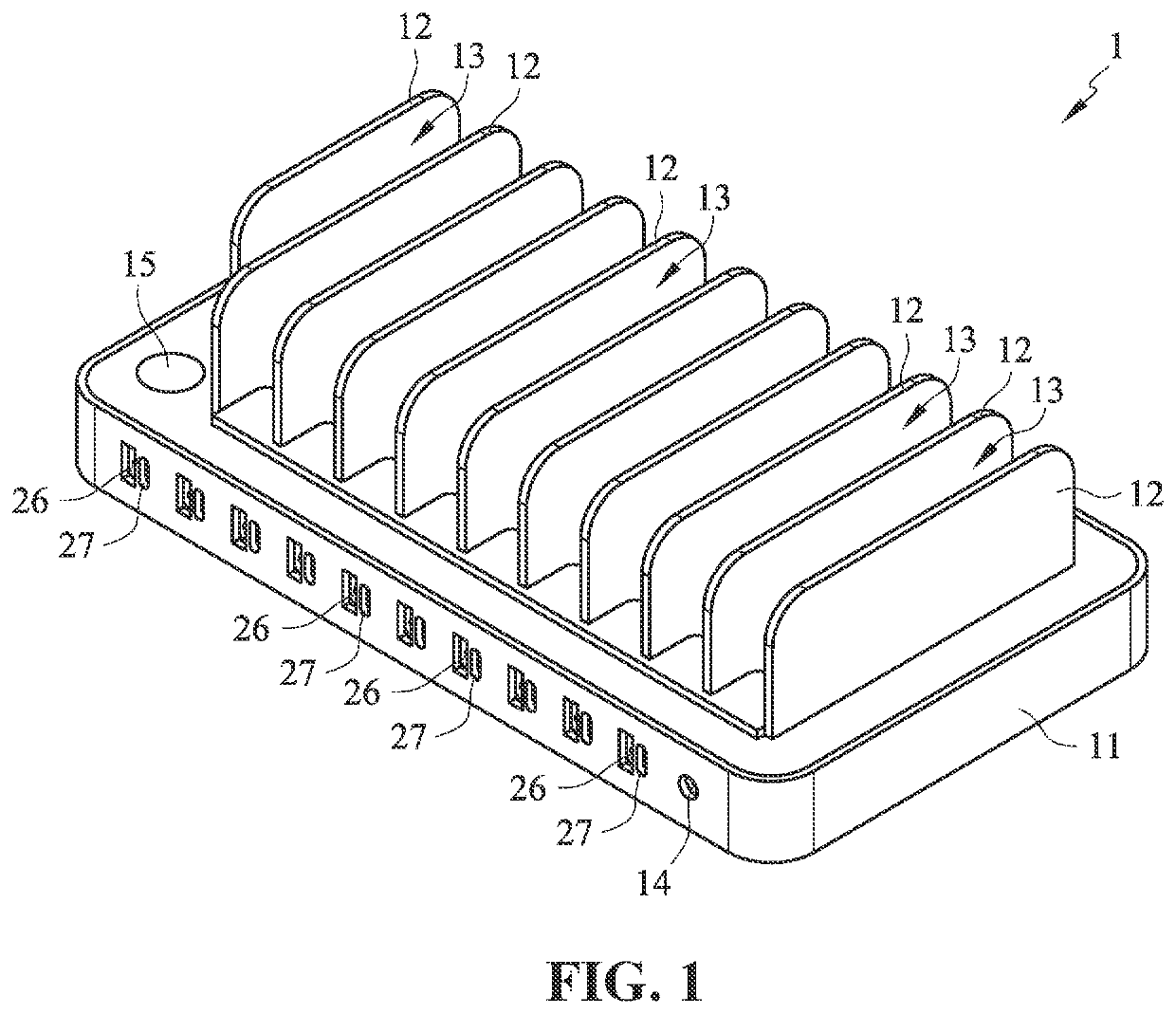
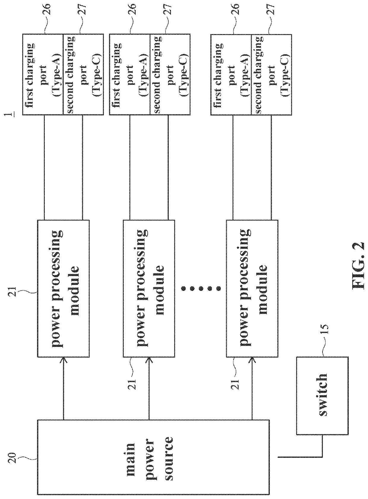
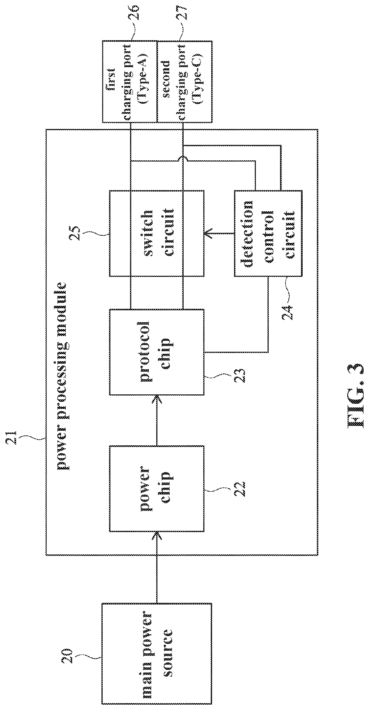
[0016]Please refer to FIG. 1 to FIG. 3. As shown in the drawings, an improved USB charging apparatus of the present invention mainly comprises a main body 1, the main body 1 comprises an outer casing 11 and a charging mechanism arranged therein. The charging mechanism comprises a main power source 20 and a plurality of power processing modules 21. Each one of the power charging modules 21 is respectively connected to two USB charging ports formed on the outer casing 11. The two USB charging ports are a first charging port 26 and a second charging port 27 having specifications different from each other respectively.

[0017]The outer casing 11 includes a power interface 14 and a switch 15 connected to the main power source 20 respectively. The power interface 14 is used for power cord connection for the introduction of power. The switch 15 is used to turn on or off the operation of the main power source 20. In this embodiment, after the main power source 20 is turned on, it is able to c...


PUM

PropertyMeasurementUnit
separation distanceaaaaaaaaaa

Abstract

An improved USB charging apparatus includes a main body and a plurality of power processing modules arranged in the main body; each one of the power processing modules having two USB charging ports connected thereto, and the two USB charging ports configured to be a first charging port and a second charging port having specifications different from each other; the first charging port and the second charging port arranged adjacent to each other; each one of the power processing modules further comprising a detection control circuit and a switch circuit, allowing each charging circuit to be provided with the charging ports of two types of specifications, such that user can choose one of the charging ports for use depending upon the actual needs. Accordingly, the improved USB charging apparatus is not limited to certain specifications of charging ports only, thereby increasing the use significantly.

Description

BACKGROUND OF THE INVENTION1. Technical Field[0001]The present invention is related to a charging apparatus of equipped with a USB interface for electronic product, and in particular, to an improved USB charging apparatus equipped with two types of specifications available for selection of one type thereof for use and also equipped with a protective design.2. Description of Related Art[0002]As there are electronic devices of numerous brands in the market, such as mobile phones, tablets and notebooks, etc., their power consumption specifications are different from each other; for example, they may be equipped with the charging ports of USB Type-C, USB Micro-B, Apple Lightning, USB Mini-B, etc., and may also use the charging cables of Type-C to Type-C, Type-A to Type-C, Type-A to Micro-B, Type-A to Lightning, Type-C to Lightning, Type-A to Mini-B, Type-C to Micro-B, etc., in conjunction. In general, the charging of the aforementioned electronic products mostly use the common Type-A or...

Claims


Application Information

Patent Timeline
Patent Type & Authority Patents(United States)
IPC IPC(8): H01M10/46H02J7/00
CPCH02J7/0044H02J7/0024H02J2207/30H02J2310/22H02J7/0013H02J7/00034
Inventor CHEN, CHIH HSINCHIU, SHIH CHE
Owner E SENSE TECH
Why Eureka
Try Eureka