Method for setting rolling mill, and rolling mill
a technology of rolling mill and setting method, which is applied in the direction of measuring device, rolling speed control device, manufacturing tool, etc., can solve the problem of difficult to directly measure such a thrust force, and achieve the effect of suppressing the occurrence of reducing the thrust force generated between rolls, and reducing the zigzagging and camber of workpieces
- Summary
- Abstract
- Description
- Claims
- Application Information
AI Technical Summary
Benefits of technology
Problems solved by technology
Method used
Image
Examples
first embodiment
2. First Embodiment
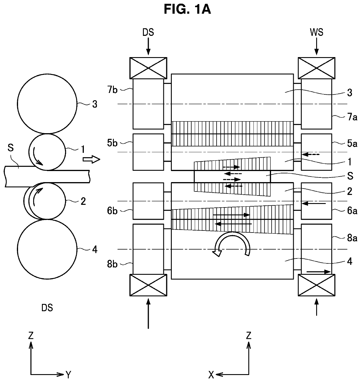
[0067]The configuration of a rolling mill and an apparatus for controlling the rolling mill, as well as a method for setting the rolling mill according to a first embodiment of the present invention will be described based on FIG. 2 to FIG. 4. In the first embodiment, before reduction position zero point adjustment or before the start of rolling, the positions of roll chocks are adjusted so as to make an inter-roll cross angle between a backup roll serving as a reference and other rolls zero, and thus rolling in which a thrust force does not arise is realized.
[0068][2-1. Configuration of Rolling Mill]
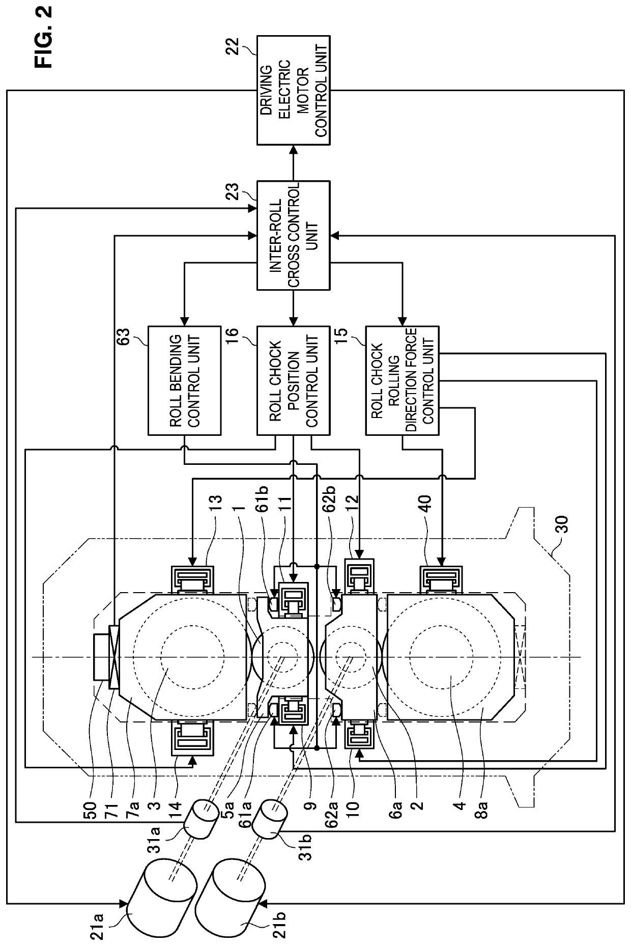
[0069]First, the rolling mill according to the present embodiment and an apparatus for controlling the rolling mill will be described based on FIG. 2. FIG. 2 is an explanatory drawing illustrating the configuration of the rolling mill according to the present embodiment and an apparatus for controlling the rolling mill. Note that, it is assumed that the rolling mill i...
second embodiment
3. Second Embodiment
[0108]Next, the configuration of a rolling mill and an apparatus for controlling the rolling mill, as well as a method for setting the rolling mill according to a second embodiment of the present invention will be described based on FIG. 5 to FIG. 7C. The rolling mill according to the second embodiment is a so-called “single drive mill” in which the upper work roll 1 and the lower work roll 2 are driven by one driving electric motor 21 through a pinion stand (not illustrated in the drawings) or the like. Therefore, in the case of adjusting roll chock positions based on the motor torque, only one roll assembly among the upper roll assembly and the lower roll assembly can be adjusted. Hereunder, the configuration of the rolling mill as well as a method for setting the rolling mill according to the present embodiment are described in detail.
[0109][3-1. Configuration of Rolling Mill]
[0110]First, the rolling mill according to the present embodiment and an apparatus fo...
example 1
[0162]A conventional method and the method of the present invention were compared in relation to reduction leveling setting that takes into consideration the influence of a thrust force due to an inter-roll cross in a so-called “twin-drive hot rolled thick-gauge plate rolling mill” in which the upper work roll 1 and the lower work roll 2 are configured to be independently rotatable that is illustrated in FIG. 2.
[0163]First, in the conventional method, without using the functions of the inter-roll crossing control unit of the present invention, replacement of housing liners and chock liners was periodically performed, and equipment management was conducted so that an inter-roll cross would not occur.
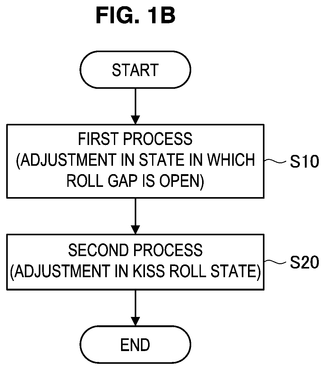
[0164]On the other hand, in the method of the present invention, using the functions of the inter-roll cross control unit according to the first embodiment that is described above, adjustment of the positions of roll chocks was performed in accordance with the processing flow illustrated ...
PUM
| Property | Measurement | Unit |
|---|---|---|
| diameter | aaaaa | aaaaa |
| width | aaaaa | aaaaa |
| width | aaaaa | aaaaa |
Abstract
Description
Claims
Application Information
 - R&D
- Intellectual Property
- Life Sciences
- Materials
- Tech Scout
- Unparalleled Data Quality
- Higher Quality Content
- 60% Fewer Hallucinations
Browse by: Latest US Patents, China's latest patents, Technical Efficacy Thesaurus, Application Domain, Technology Topic, Popular Technical Reports.
© 2025 PatSnap. All rights reserved.Legal|Privacy policy|Modern Slavery Act Transparency Statement|Sitemap|About US| Contact US: help@patsnap.com


