Dynamic eye fixation for retinal imaging

a retinal imaging and dynamic technology, applied in the field of retinal imaging technologies, can solve the problems of reducing image fidelity, affecting image fidelity, and causing optical aberrations or image artifacts

Active Publication Date: 2022-07-19
VERILY LIFE SCI LLC
View PDF25 Cites 3 Cited by
  • Summary
  • Abstract
  • Description
  • Claims
  • Application Information

AI Technical Summary

Problems solved by technology

Bright illumination of the posterior interior surface of the eye (i.e., retina) through the pupil improves image fidelity but often creates optical aberrations or image artifacts, such as corneal reflections, iris reflections, or lens flare, if the retinal camera and illumination source are not adequately aligned with the eye.
Simply increasing the brightness of the illumination does not overcome these problems, but rather makes the optical artifacts more pronounced, which undermines the goal of improving image fidelity.
The small size of conventional eyeboxes makes retinal camera alignment difficult and patient interactions during the alignment process often strained.
However, these stages tend to be mechanically complex and substantially drive up the cost of a retinal imaging platform.

Method used


Image

  • Dynamic eye fixation for retinal imaging
  • Dynamic eye fixation for retinal imaging
  • Dynamic eye fixation for retinal imaging

Examples


Embodiment Construction

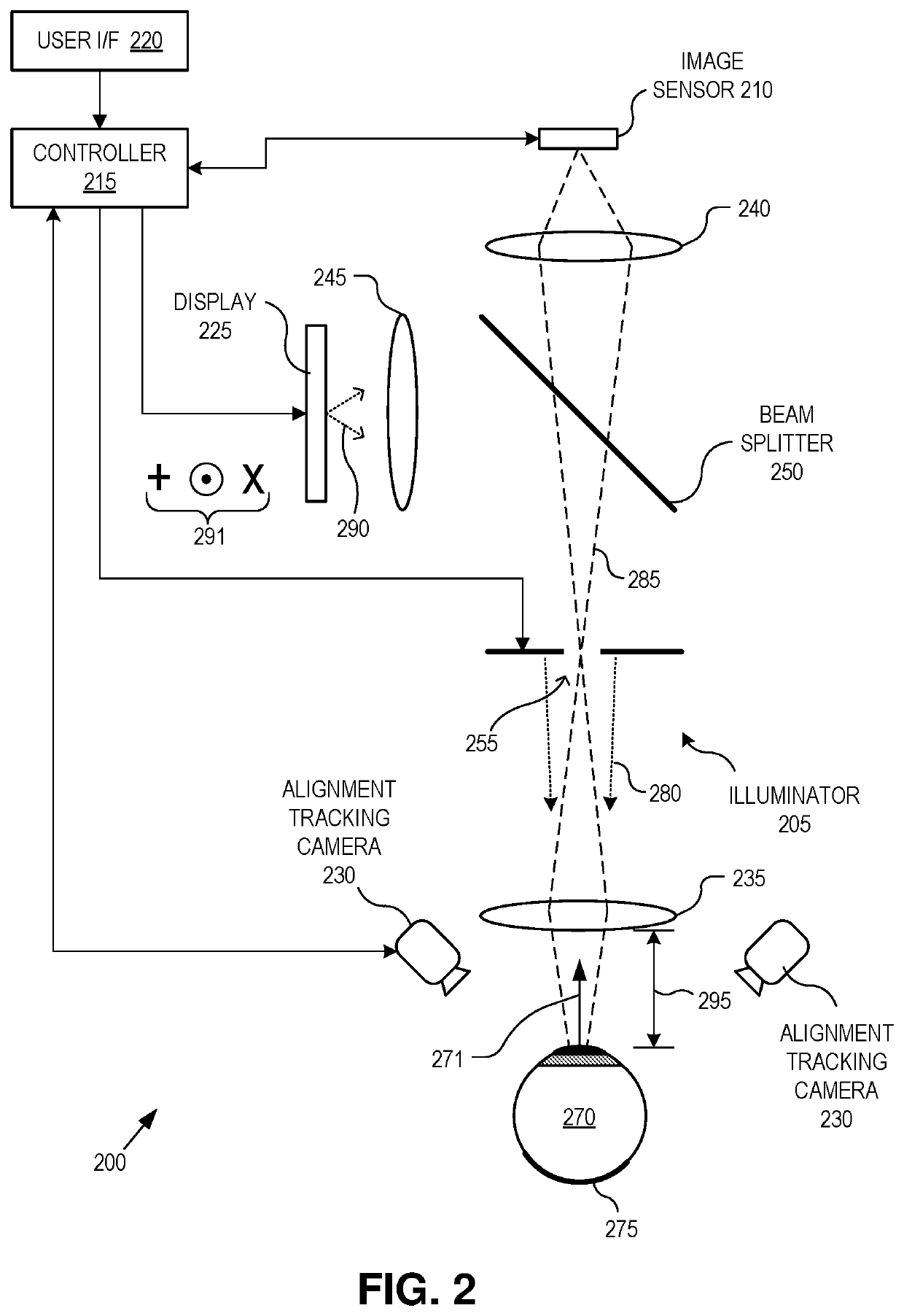
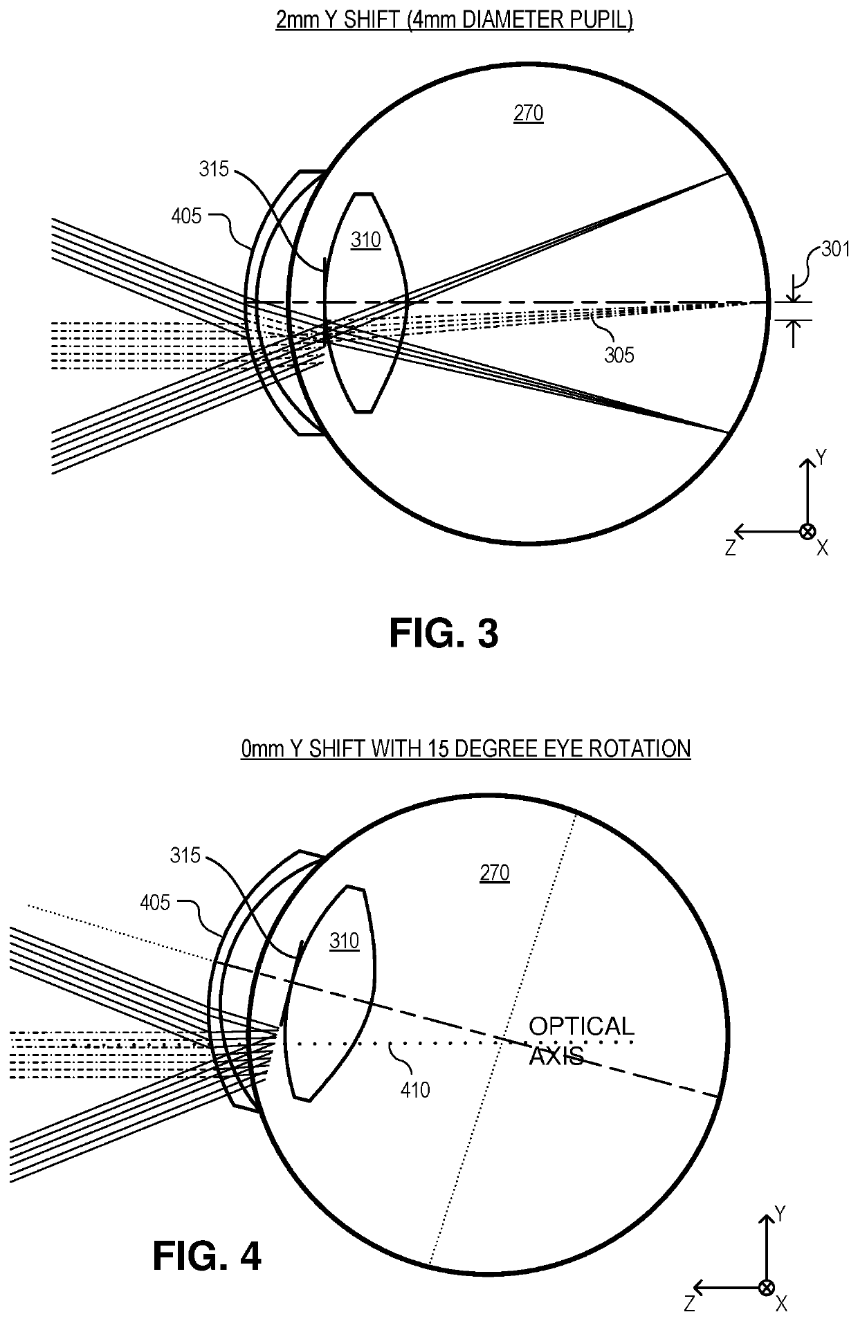
[0018]Embodiments of an apparatus, system, and method of operation for dynamically adjusting a fixation target of a retinal camera system to encourage a compensating eye roll maneuver that offsets lateral misalignment between the retinal camera system and an eye are described herein. In the following description numerous specific details are set forth to provide a thorough understanding of the embodiments. One skilled in the relevant art will recognize, however, that the techniques described herein can be practiced without one or more of the specific details, or with other methods, components, materials, etc. In other instances, well-known structures, materials, or operations are not shown or described in detail to avoid obscuring certain aspects.

[0019]Reference throughout this specification to “one embodiment” or “an embodiment” means that a particular feature, structure, or characteristic described in connection with the embodiment is included in at least one embodiment of the pre...


PUM


Abstract

A retinal imaging system includes an eyepiece lens assembly, an image sensor, a dynamic fixation target viewable through the eyepiece lens assembly, and a controller coupled to the image sensor and the dynamic fixation target. The controller includes logic that causes the retinal imaging system to perform operations including: acquiring a first image of the eye, analyzing the first image to determine whether a lateral misalignment between the eye and the eyepiece lens assembly is greater than a threshold misalignment, in response to determining the lateral misalignment is greater than the threshold misalignment, adjusting a visual position of the dynamic fixation target to encourage the eye to rotate in a direction that compensates for the lateral misalignment, and acquiring the retinal image of the eye while the eye is encouraged to rotate towards the direction that compensates for the lateral misalignment.

Description

CROSS-REFERENCE TO RELATED APPLICATIONS[0001]This application claims the benefit of U.S. Application No. 62 / 753,570, filed on Oct. 31, 2018, the contents of which are incorporated herein by reference.TECHNICAL FIELD[0002]This disclosure relates generally to retinal imaging technologies, and in particular but not exclusively, relates to fixation targets for retinal imaging.BACKGROUND INFORMATION[0003]Retinal imaging is a part of basic eye exams for screening, field diagnosis, and progress monitoring of many retinal diseases. A high fidelity retinal image is important for accurate screening, diagnosis, and monitoring. Bright illumination of the posterior interior surface of the eye (i.e., retina) through the pupil improves image fidelity but often creates optical aberrations or image artifacts, such as corneal reflections, iris reflections, or lens flare, if the retinal camera and illumination source are not adequately aligned with the eye. Simply increasing the brightness of the illu...

Claims


Application Information

Patent Timeline
Patent Type & Authority Patents(United States)
IPC IPC(8): A61B3/12A61B3/14A61B3/00G06T7/73G06T7/20G06T7/00
CPCA61B3/12A61B3/0091A61B3/14G06T7/0016G06T7/20G06T7/74G06T2207/10048G06T2207/30041A61B3/0025G06T7/73A61B3/152
Inventor GLIK, ELIEZERKAVUSI, SAM
Owner VERILY LIFE SCI LLC
Why Eureka
Try Eureka