
Fracture reduction method and parallel external fixator for fracture reduction

a fracture reduction and fixator technology, applied in the field of orthopaedic external fixation, can solve the problems of low accuracy of strut adjustment, decrease of fixator stability, and difficulty in predicting the possible interference between the bone segments during fracture reduction, so as to avoid subjective and objective errors, effectively avoid the risk of fracture segment interference, and effectively avoid the effect of interference between the struts

Active Publication Date: 2022-03-29
BEIJING NATON MEDICAL TECH HLDG CO LTD
View PDF30 Cites 0 Cited by
  • Summary
  • Abstract
  • Description
  • Claims
  • Application Information

AI Technical Summary

Benefits of technology

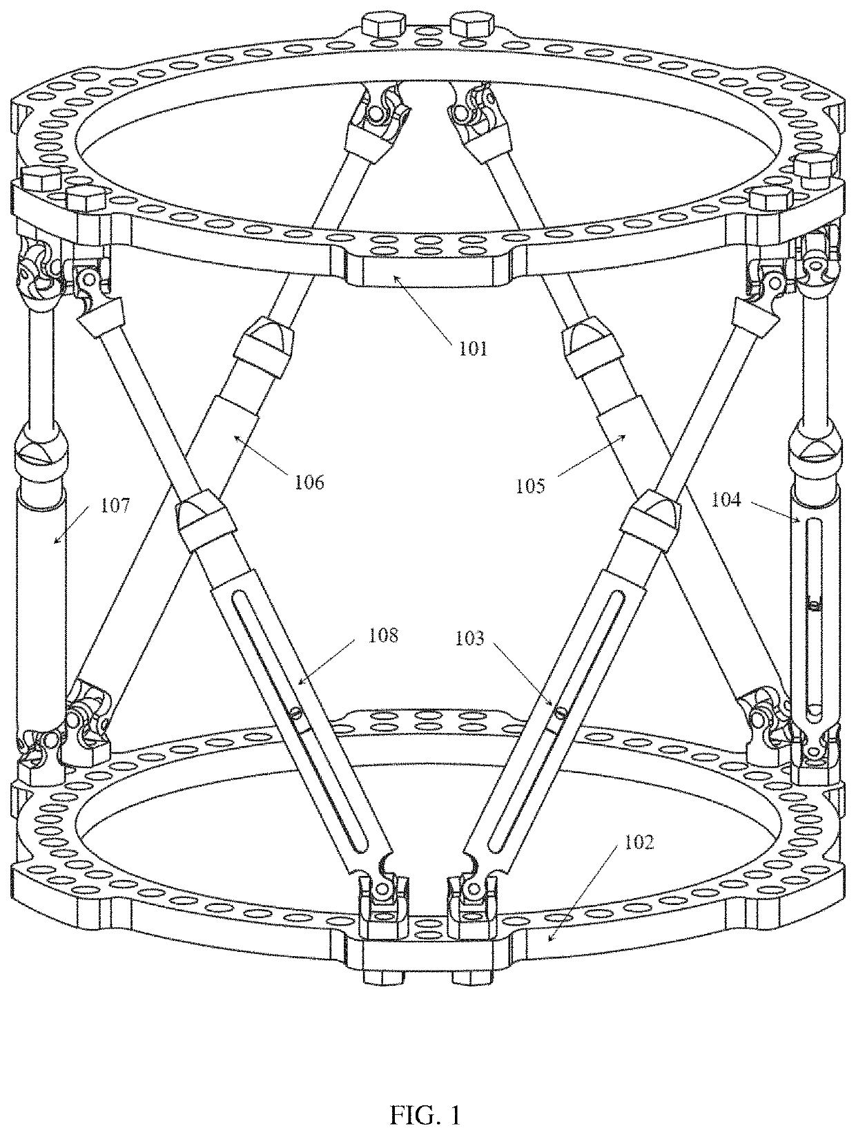
[0041]The spherical hinge comprises a connecting shaft whose upper end is a threaded shaft, and the threaded shaft of the connecting shaft is capable of inserting into one outer ring connecting hole or one inner ring connecting hole in the proximal fixation ring and is fixedly connected with the proximal fixation ring through a nut; and the lower end of the connecting shaft is pivotally connected with the both ends of the long shaft of a cross-shaft component, the cross-shaft component is mounted at the upper part of a revolute connecting sleeve, the outer ends of the other two short shafts of the cross-shaft component are respectively and pivotally connected into the hole of the revolute connecting sleeve, a plain bearing is pivotally mounted in the cavity of the lower part of the revolute connecting sleeve, the inner ring of the plain bearing is in fixed connection with the upper section of a screw rod, where the top of the screw rod inserts into the plain bearing and is fixedly connected with an anti-loosening nut to prevent the threaded connection between the plain bearing and the screw rod from loosening; a back nut is connected with the internal thread at the bottom of the cavity of the revolute connecting sleeve through an external thread, the inner hole of the back nut and the outer surface of the screw rod have a certain clearance, enabling the screw rod and the back nut a relatively free rotation, and the back nut is capable of axially positioning the plain bearing.
[0048](6) The driving joint of the strut of the external fixator has a locking structure, which can lock the length of the strut and eliminate the tiny gap of the driving joint, thus improving the stability of the external fixator in fracture fixation.

Problems solved by technology

The parallel external fixators provided by the above patents has the following defects: 1) the connection between the six struts and the fixation rings is only in a circularly symmetric manner, and interference between the struts and the bone pins occurs occasionally during clinical mounting; 2) the scale resolution of the driving joint in the strut is not high, and the strut adjustment accuracy is low; 3) the driving joint of the strut cannot be locked in the fracture fixation state, and the gap leads to the decrease of the stability of the fixator.
The reduction methods provided by the above patents have the following defects: 1) the X-ray frontal and lateral films cannot reflect the rotation deformity around the diaphysis axis of the fracture site, and factors such as the X-ray image shooting angle, shooting distance, and the patient's limb placement cannot be standardized; 2) there are many subjective and objective errors in manual measurement of X-ray images; 3) such methods fail to visualize fracture reduction movement, making it difficult to predict the possible interference between the bone segments during fracture reduction.
Therefore, a heretofore unaddressed need exists in the art to address the aforementioned deficiencies and inadequacies.

Method used


Image

  • Fracture reduction method and parallel external fixator for fracture reduction
  • Fracture reduction method and parallel external fixator for fracture reduction
  • Fracture reduction method and parallel external fixator for fracture reduction

Examples


Embodiment Construction

[0073]The present invention will now be described more fully hereinafter with reference to the accompanying drawings, in which exemplary embodiments of the present invention are shown. The present invention may, however, be embodied in many different forms and should not be construed as limited to the embodiments set forth herein. Rather, these embodiments are provided so that this disclosure is thorough and complete, and will fully convey the scope of the invention to those skilled in the art. Like reference numerals refer to like elements throughout. The embodiments of the present invention will be described below in detail with reference to the drawings.

[0074]A fracture reduction method provided by the present invention is applicable to fracture reduction or limb deformity osteotomy and correction by using the existing six-chain ring-shaped parallel external fixator (such as patent CN201120414672, U.S. Pat. No. 8,454,604 or 6,030,386) or a parallel external fixator provided by th...


PUM


Abstract

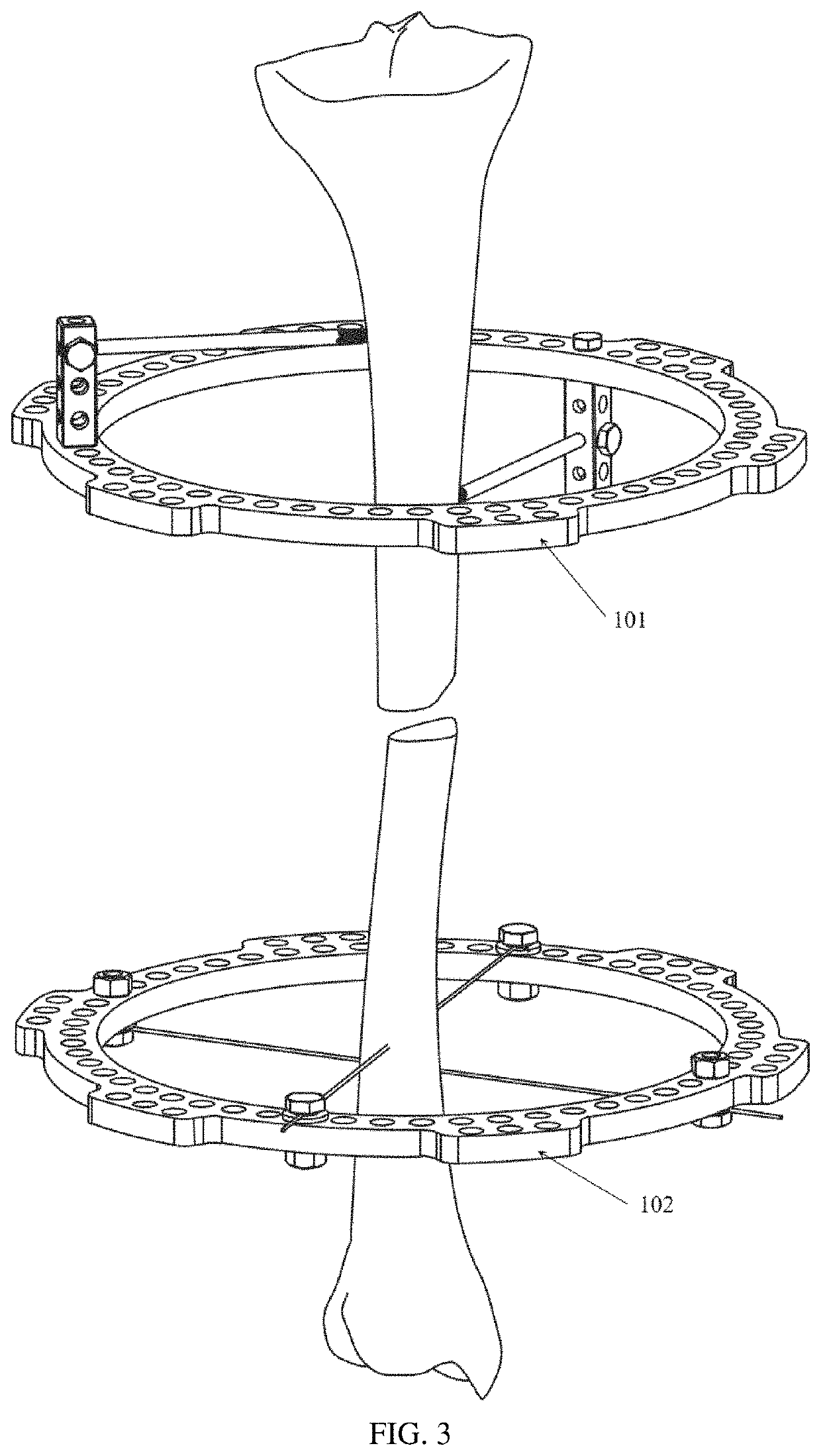
A fracture reduction method and a parallel external fixator for fracture reduction for realizing the method, the fracture reduction method being used for existing six-chain ring-shaped parallel external fixators in minimally invasive fracture reduction or osteotomy of limbs. The parallel external fixator comprises two fixation rings, six struts and six markers, the fixation rings are arranged with a plurality of connecting holes, the struts are arranged with a spherical hinge, a driving joint (1302), a quick-mounting component and a universal hinge, the markers comprise marker balls and a pin shaft. The parallel external fixator can improve the treatment accuracy, reliability and operation convenience.

Description

CROSS-REFERENCE TO RELATED APPLICATIONS[0001]This application is a national stage application of PCT Application No. PCT / CN2018 / 102719. This application claims priority from PCT Application No. PCT / CN2018 / 102719, filed Aug. 28, 2018, CN Application No. CN 201810567844.2 filed Jun. 5, 2018, the contents of which are incorporated herein in the entirety by reference.[0002]Some references, which may include patents, patent applications, and various publications, are cited and discussed in the description of the present disclosure. The citation and / or discussion of such references is provided merely to clarify the description of the present disclosure and is not an admission that any such reference is “prior art” to the present disclosure described herein. All references cited and discussed in this specification are incorporated herein by reference in their entireties and to the same extent as if each reference was individually incorporated by reference.FIELD OF THE INVENTION[0003]The pr...

Claims


Application Information

Patent Timeline
Patent Type & Authority Patents(United States)
IPC IPC(8): A61B17/64
CPCA61B17/6441A61B17/6475A61B17/62A61B17/64A61B17/645A61B34/10A61B2034/107A61B2034/108A61B17/66A61B2017/00991A61B17/6416A61B2034/101A61B2090/3966
Inventor SUN, TAOLIU, SIDASONG, YIMINYAN, WEI
Owner BEIJING NATON MEDICAL TECH HLDG CO LTD
Learn More