Flow rate scale field calibration for balancing valve

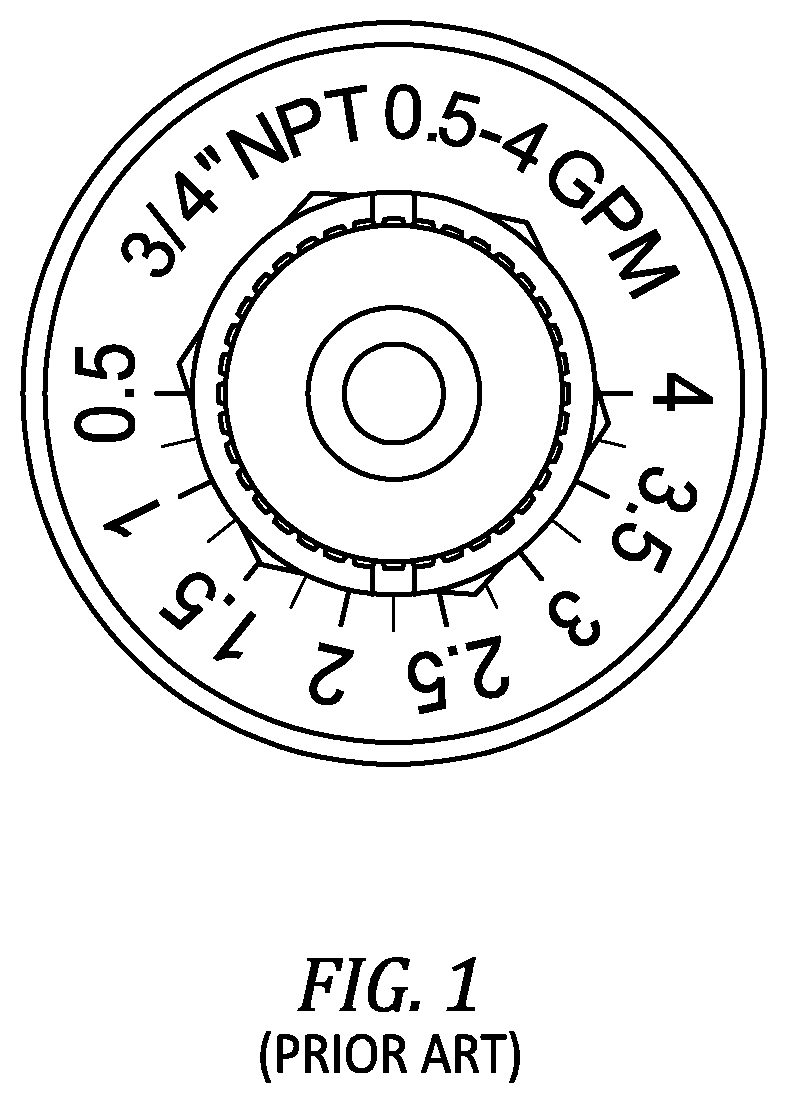
a flow rate scale and balancing valve technology, applied in the field of balancing valves, can solve the problems of adding a significant amount of time to system balancing, and difficult visual interpolation between the 8 numerically written increments and hash marks

Active Publication Date: 2022-03-15
FLUID HANDLING
View PDF42 Cites 0 Cited by
  • Summary
  • Abstract
  • Description
  • Claims
  • Application Information

AI Technical Summary

Benefits of technology

The present invention provides a balancing valve with a feature that shows the exact flow rate for a chosen setting in the appropriate unit of measure of flow rate. The valve allows users to set a desired flow rate in one operation. The flow characteristics of the valve are transcribed onto a scale to provide desired increments of flow settings. The valve also has hash marks that correspond to calibrations in tenths of gallons per minute, which makes it easier to visually interpolate between the hash marks. This makes it easier to achieve the desired flow rate and ensures consistent and accurate flow. The valve also does not mix actual flow calibrations between different indicators. Overall, the balancing valve according to the invention provides more increments, indicators, and known calibrations in tenths of gallons per minute, leading to greater flow accuracy and consistency.

Problems solved by technology

For complicated systems, this could add a significant amount of time for system balancing.
Because of this, the known balancing valve makes it harder to visually interpolate between the hash marks in tenths of a GPM.
In fact, a user must try to visually interpolate every intermediate setting in tenths of a GPM, which makes it harder to visually interpolate between the 8 numerically written increments and hash marks.
Both of these shortcomings lead to less flow accuracy when the user sets the flow rate of the known balancing valve.

Method used


Image

  • Flow rate scale field calibration for balancing valve
  • Flow rate scale field calibration for balancing valve
  • Flow rate scale field calibration for balancing valve

Examples


Embodiment Construction

FIGS. 2a to 2c

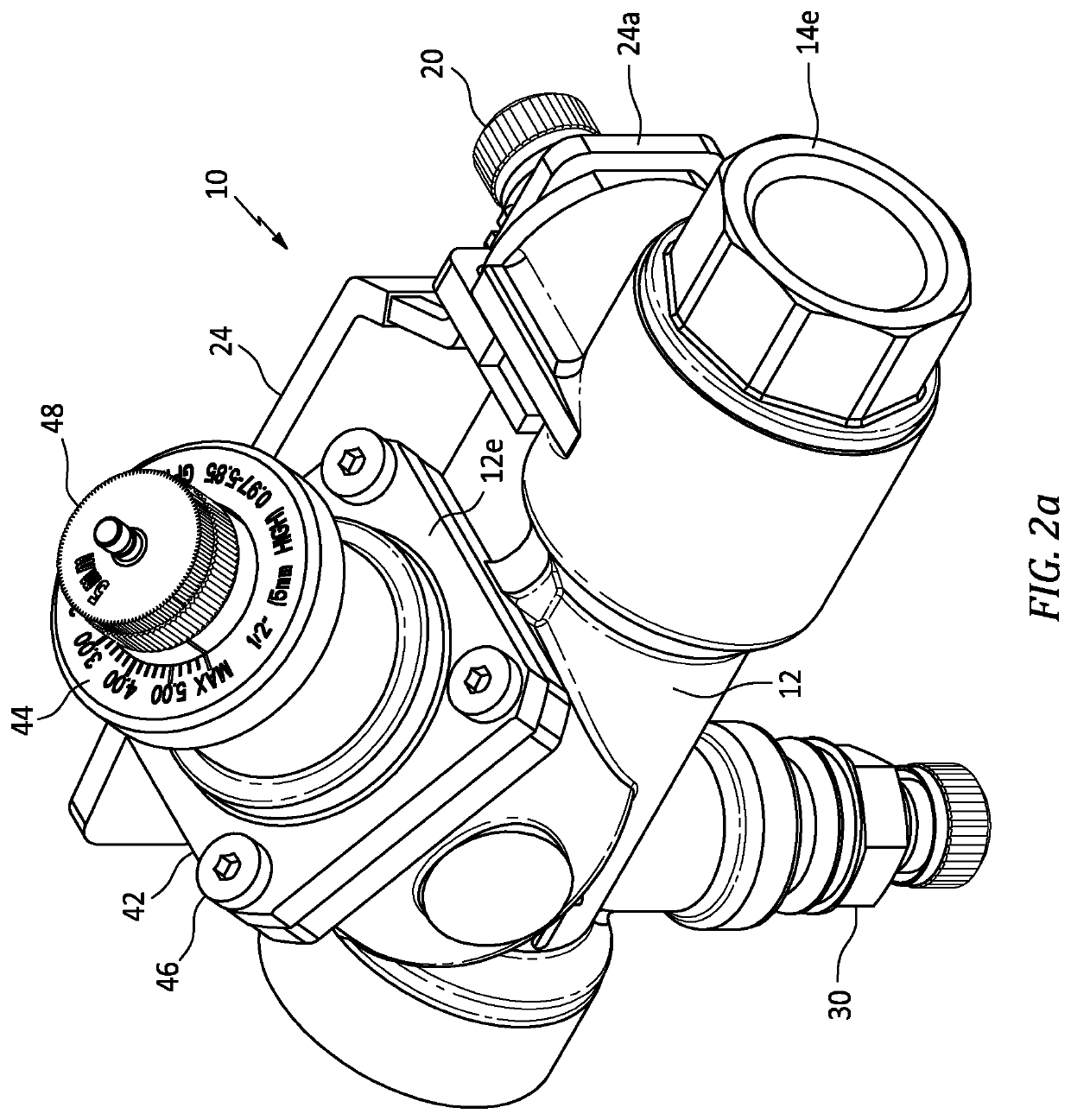
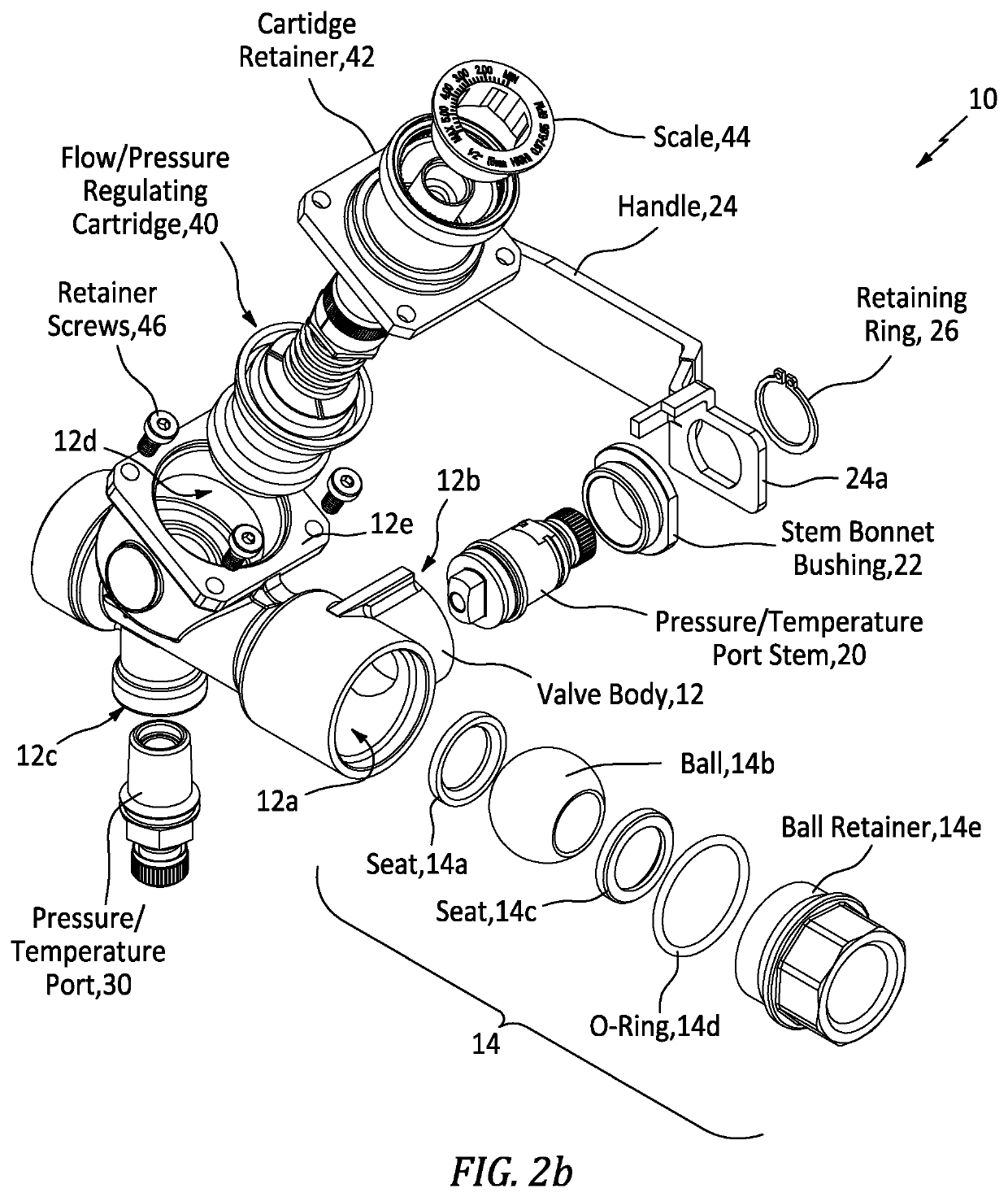
[0030]FIG. 2a-2c show apparatus generally indicated as 10 in the form of part of a balancing valve having a flow rate scale field calibration implementation according to some embodiments of the present invention. FIGS. 2a and 2b shows the parts and components of the balancing valve 10, and FIG. 2c shows a scale or indicator and a knob that forms part of the balancing valve shown in FIGS. 2a and 2b.

[0031]In FIGS. 2a and 2b, the balancing valve 10 includes a valve body / member 12 configured or formed with a first cavity or chamber generally indicated as 12a to receive a combination or arrangement generally indicated as 14 of a seat 14a, a ball 14b, a seat 14c, an O-ring 14d and a ball retainer 14e. The valve body 12 is also formed with a second cavity or chamber generally indicated as 12b and coupled to the first cavity or chamber 12a. The second cavity or chamber 12b is configured to receive a combination of a pressure / temperature port stem 20 and a stem bonnet bushing...


PUM


Abstract

A balance or flow limiting valve features a valve body / member having a flow rate indicator / scale containing setting having printed flow rates calibrated in units of measure in volume per time increment between a minimum flow rate position (MIN) and a maximum flow rate position (MAX); and a knob / handle having a position indicator and being moveable to any continuous position on the flow rate indicator / scale between MIN and MAX in response to a user applied force, where the relationship between the flow rate indicator / scale and the position indicator is based on calibrated flow characteristics of the balance or flow limiting valve. The user can set an exact desired flow rate in one operation by moving the knob / handle to a desired position between MIN and MAX without consulting a printed flow curve or balance calculator to determine the desired exact flow rate.

Description

CROSS-REFERENCE TO RELATED APPLICATION[0001]This application is a continuation of U.S. patent application Ser. No. 13 / 668,633 filed on 5 Nov. 2012, which application claims benefit to U.S. provisional patent application Ser. No. 61 / 586,372, filed 13 Jan. 2012, which is hereby incorporated by reference in its entirety.BACKGROUND OF THE INVENTION1. Field of the Invention[0002]The present invention relates to a balancing valve; and more particularly to a new technique for providing a flow rate scale field calibration for such a balancing valve.2. Brief Description of Related Art[0003]Presently, flow setting with balance or flow limiting valves in a hydronic system requires the user to first set the valve position by turning a knob or handle on the valve to a position indicated on an adjacent scale. Current valve scales have either an arbitrary numbering scheme, or a number relating to the percentage of maximum rated flow of the specific valve. The user then must consult either a printe...

Claims


Application Information

Patent Timeline
Patent Type & Authority Patents(United States)
IPC IPC(8): F16K37/00G05D7/01
CPCF16K37/0016G05D7/01Y10T137/8225Y10T137/8309
Inventor EVANS, JR., STANLEY PAULROSCA, FLORINHUSE, GLENN EDWARDKAHN, DONALD ARTHUR
Owner FLUID HANDLING
Why Eureka
Try Eureka