
Negative pressure wound apposition dressing system

a dressing system and negative pressure technology, applied in the field of mammalian tissue medical treatment and therapy, can solve the problems of affecting the healing effect of surgical wounds, affecting the patient's recovery, so as to promote the healing of surgical wounds, promote tissue oxygenation, and promote the effect of negative pressur

Active Publication Date: 2022-02-22
MIDWEST TRAINING & DEV SERVICES LLC
View PDF15 Cites 1 Cited by
  • Summary
  • Abstract
  • Description
  • Claims
  • Application Information

AI Technical Summary

Benefits of technology

[0011]In one embodiment, the present disclosure provides a negative pressure wound apposition dressing, device and system useful for closure and promoting healing of surgical, non-surgical, and traumatic wounds, and the like. One key aspect of said dressing, device and system is that they are completely mechanical, and do not include any electronic parts or require the use of any electronic sources. In another aspect, said dressing, device and system provide the benefit of negative pressure promotion of tissue oxygenation. In another aspect, said dressing, device and system are adaptable to be used in a modular manner. In another aspect, said negative pressure wound apposition dressing, device and system are designed to be easily operated by the patient when that is desired or required.
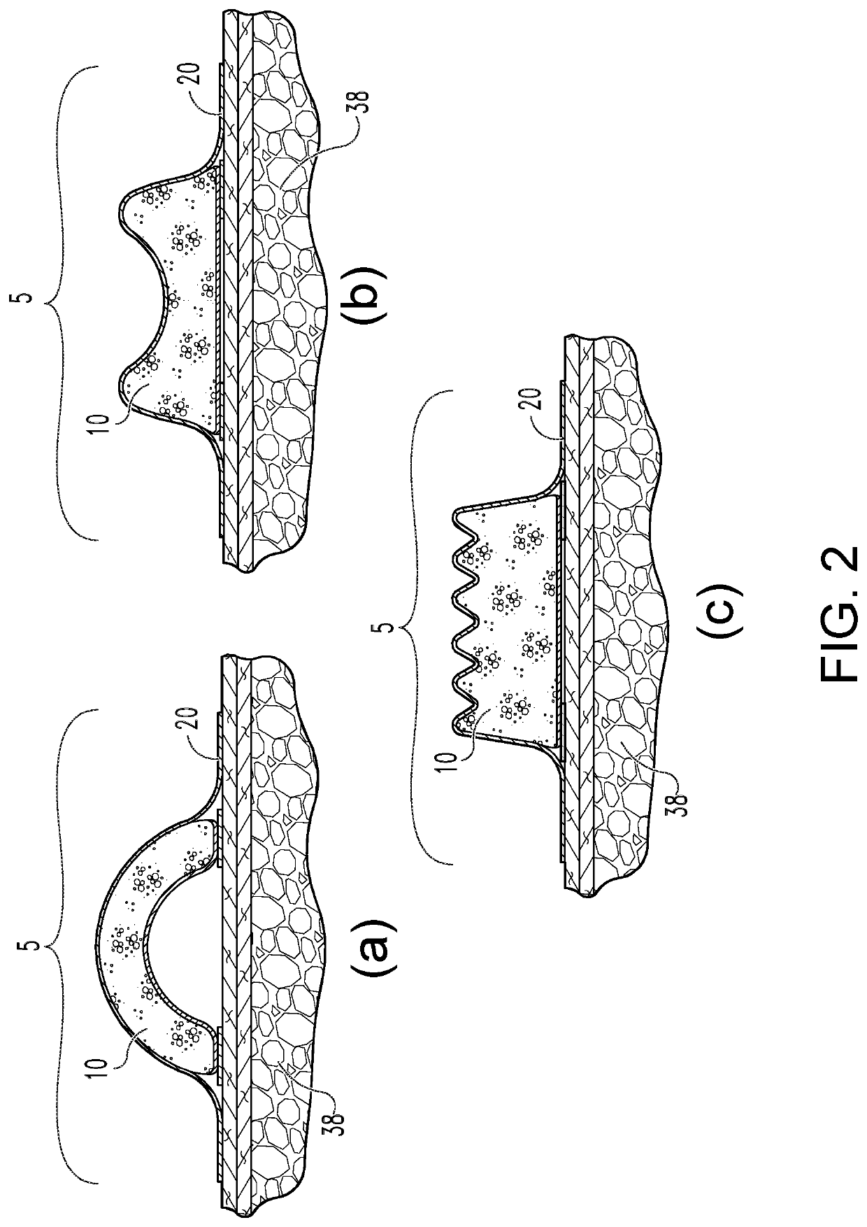
[0014]In another embodiment, the invention comprises a drape, made of plastic or other suitable material, including occlusive, clear materials; this drape goes over and overlies the sponge. In one aspect, this drape may be designed to possess, either partially or wholly, an “accordion-like” shape; this accordion-like shape would also help to draw the wound edges inwardly and provide further reduction in wound tension and apposition of the wound edges, enhancing the healing process. Additionally, the invention comprises an adhesive tape edge along the edges of the dressing, similar to the adhesive tape edge in existing NPWT devices; when the dressing is positioned over the wound, this adhesive tape edge would run parallel to the wound and would provide a seal along the length of the dressing.
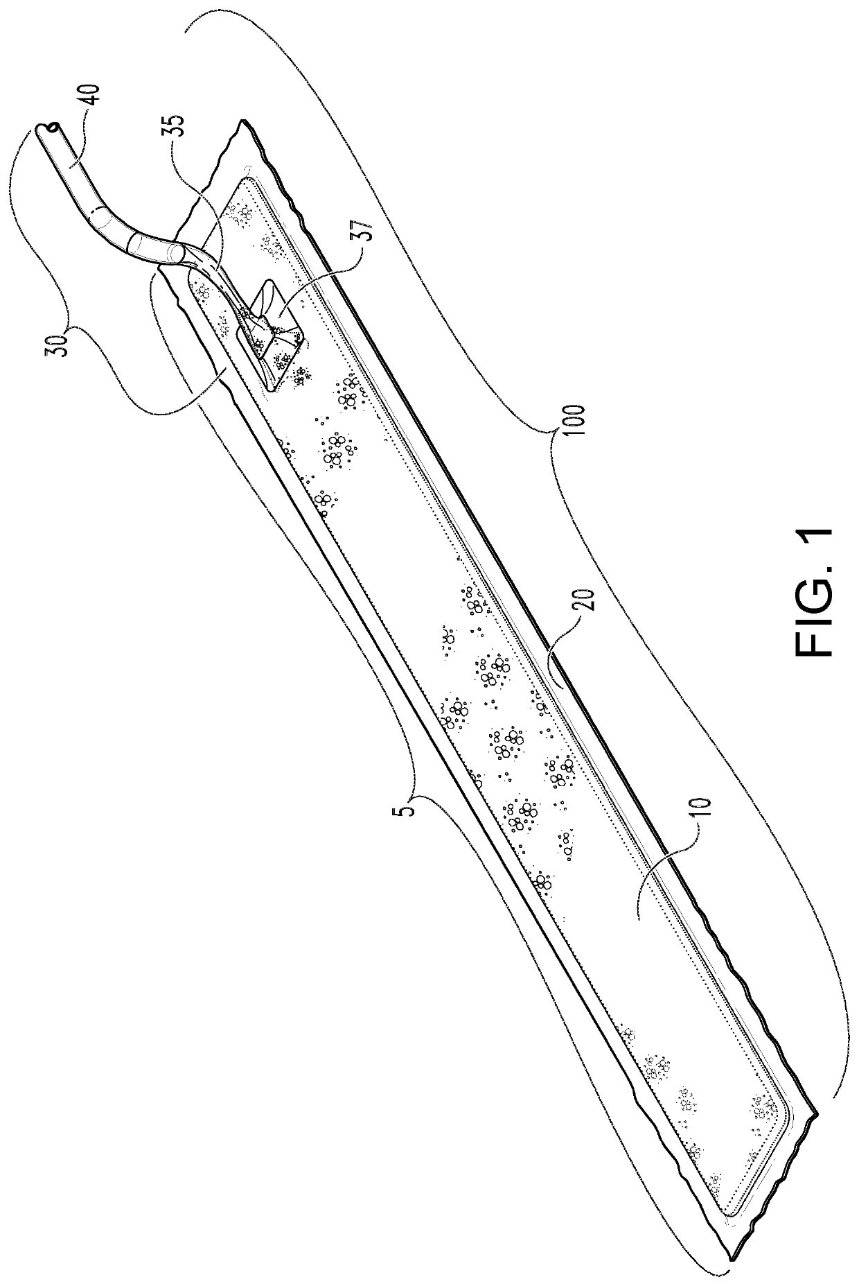
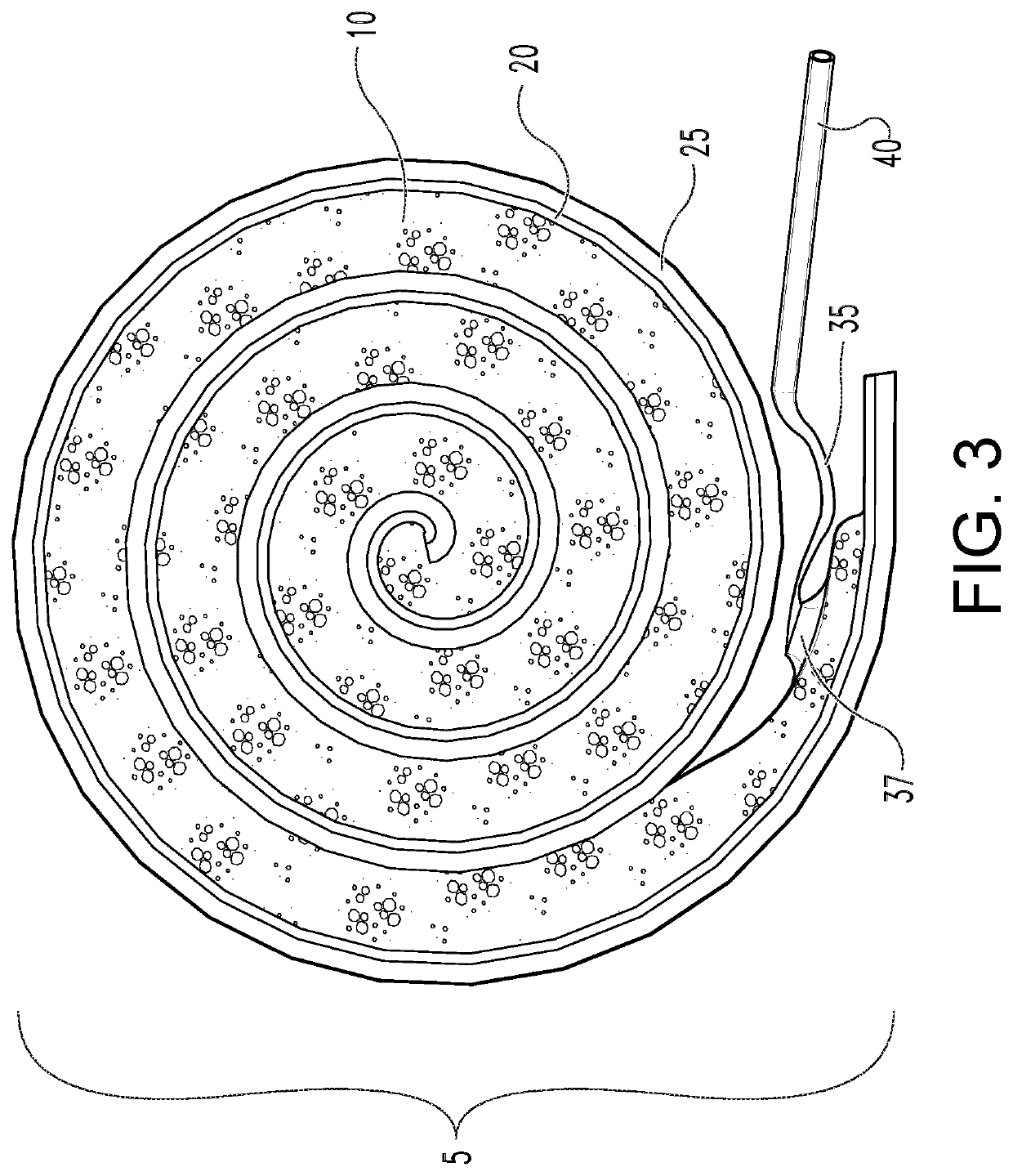
[0015]In another embodiment, the invention comprises a means by which the sponge and tape / apron may be provided as a long roll, such as, illustratively, a roll resembling rolled-up insulation for a building, and the like. A suction / pad interface would be designed to be positioned at the beginning of the long roll, which may be unrolled quickly on the wound. The invention may also comprise a “peel-away” layer on the back of the apron making the apron stick to the skin. If the need arises to change the location of the suction / pad interface, then the dressing can be readily cut and sealed with any type of available, inexpensive medical dressing, such as the transparent medical dressings manufactured by 3M known as Tegaderm™, which are typically found in every operating room. In addition, if the need for a longer dressing arises, these can then be lined in a “daisy chain” manner via the use of a Tegaderm™.
[0016]In another embodiment, the invention comprises a length of vacuum or suction tubing leading from the dressing sponge to the vacuum source. One important aspect is that the junction of the vacuum tubing to the sponge strip is designed to be rectangular and flat so as to decrease the pressure exerted by the junction and tubing on the wound, which cause pressure and pressure necrosis underneath. In many instances wounds may experience some sort of pressure, such as, illustratively, from the weight of an overhanging stomach, clothing, or an ACE wrap. Thus, in this invention the tubing in the critical area is flat and stented open with a small amount of the same sponge material, so as to decrease pressure on the wound. Beyond the critical area, the tubing may be more rigid.

Problems solved by technology

If the negative pressure is too great, the terminal capillaries collapse.
If the negative pressure is too slight, there is no benefit observed.
For example, some available NPWT devices do not include any fluid reservoir to collect fluids.
They are bulky, expensive, and noisy, bothersome to patients.
Furthermore, many types are permeable to gases and fluids, and / or do not provide enough suction to be sufficiently beneficial toward wound healing.
Physicians and other medical professionals often report that these devices can be very cumbersome to use, are prone to failure due to discharged batteries, and are costly for insurance and manufacturers.
The rigid plastic and round tubing have been known to occasionally cause pressure and pressure necrosis underneath, which are outcomes that are opposite to the goal of using a vacuum device.
In addition, the current vacuum devices have been known to fail quite often.
This can be due to a patient that lacks the savviness to recharge the unit, or simply due to a faulty unit.
When a vacuum device fails, the result is very poor for wound healing, as a wet sponge stays placed on the incision for a prolonged period of time, possibly up to a week.
Also, patients often do not realize when the collection canister is full, which may cause the vacuum to fail.
In addition, the canisters may have a good deal of stagnant fluid within, which can create the stigma of an odor.
They are reportedly cleaned between uses, but there are simply too many crevices and parts for these to not harbor bacteria from the prior users.
It is not unusual for physicians and other medical professionals to waste much time in the operating room trying to troubleshoot a vacuum device, only to find out that it was a faulty refurbished unit.
However, these, and numerous others like them, suffer from a variety of unfavorable and limiting features, making them costly to produce and / or purchase, and / or potentially impractical or cumbersome to use.

Method used


Image

  • Negative pressure wound apposition dressing system
  • Negative pressure wound apposition dressing system
  • Negative pressure wound apposition dressing system

Examples


Embodiment Construction

[0034]Before the present details of the invention are disclosed and described, it is to be understood that this invention is not limited to the specific components, methods, and implementation, or to the precise arrangements and instrumentalities shown, as such may, of course, vary while remaining within the scope and spirit of the invention. It is also to be understood that the terminology used herein is for the purpose of describing particular implementations only, and to assist in understanding the disclosure, and is not intended to be limiting.

[0035]The figures illustrating the negative pressure wound apposition dressing, device and system of the invention show some mechanical elements that partially or fully resemble standard mechanical elements used in the art and that will be recognized by one skilled in the art. The detailed descriptions of these elements are presented herein only to the degree necessary to facilitate an understanding of the novel features of the present inv...


PUM


Abstract

The present disclosure relates generally to the field of medical treatment and therapy of mammalian tissue. More specifically, it relates to coverings and / or dressings that provide negative pressure at mammalian tissue sites, such as at one or more sites of surgical, non-surgical, and / or traumatic wounds, to promote closure and healing of the wounds. A key embodiment of the disclosed invention entails the use of a dressing that comprises a sponge that is shaped so as to create a vector force inward bringing wound edges together to promote healing, especially upon application of negative pressure. Other key features of the disclosed invention are its simplicity, its low cost, and that it is completely mechanical and lacks the need for any electronic components. The disclosure also relates to devices, systems, kits and methods for providing said negative pressure at said mammalian tissue sites and promote healing.

Description

CROSS-REFERENCE TO RELATED APPLICATIONS[0001]This application claims priority under 35 USC § 119(e) to U.S. Provisional Patent Application Ser. No. 62 / 672,283, filed on May 16, 2018, the disclosure of which is incorporated herein by reference in its entirety.FIELD OF INVENTION[0002]The present disclosure relates generally to the field of medical treatment and therapy of mammalian tissue. More specifically, it relates to coverings and / or dressings that provide negative pressure at mammalian tissue sites, such as at one or more sites of surgical, non-surgical, and / or traumatic wounds, to promote closure and healing of the wounds. The disclosure also relates to a device, system, and method for providing said negative pressure at said mammalian tissue sites.BACKGROUND OF INVENTION[0003]Although the invention disclosed in the following pertains primarily to treatment and therapy of wounds in mammalian subjects via the application of negative pressure, it is to be understood that, as cont...

Claims


Application Information

Patent Timeline
Patent Type & Authority Patents(United States)
IPC IPC(8): A61M1/00A61F13/00A61F13/02
CPCA61F13/00068A61M1/0003A61M1/90A61F13/023A61F2013/00174A61F2013/00536A61M1/74A61F13/0216A61M2205/183A61M2205/075A61M2205/073A61M2209/088A61M1/732A61M1/81A61M1/80A61M2205/581A61M1/984A61M1/67A61M1/915A61M1/962A61M1/60A61M1/913A61M1/98
Inventor ZOCHOWSKI, CHRISTOPHER G.BEREND, KEITH R.
Owner MIDWEST TRAINING & DEV SERVICES LLC
Learn More