Ceramic implant

a ceramic implant and implant technology, applied in the field of ceramic implants, can solve the problems of inability to meet the production tolerances, grinding techniques, design of the internal bore of the implant, etc., and achieve the effects of improving the mechanical stability of the implant, improving the freedom of design of dental prosthetic care parts, and small corner radii

Active Publication Date: 2022-01-25
DENTALPOINT
View PDF8 Cites 0 Cited by
  • Summary
  • Abstract
  • Description
  • Claims
  • Application Information

AI Technical Summary

Benefits of technology

[0023]The difference between the grinding operation used so far and the milling or drilling operation implemented in the present invention can be seen in that the base body of sintered, hard zirconium dioxide is in accordance with the inventive method machined down. In this way, very time-consuming machining operations such as, for example, grinding a concave corner radius in a receptacle opening of an implant can be avoided. The machining of the sintered zirconium dioxide ceramic is then no longer subject to the restrictions of the grinding technique, but rather based on metalworking. The milling head used for the milling operation or the drilling head used for the drilling operation has a diameter of 0.5-5 mm and is made of full diamond, preferably a polycrystalline diamond. In comparison with a grinding tool, the milling head or the drilling head has a surface geometry that makes it possible to machine the zirconium dioxide ceramic. In this case, the surface geometry is realized in such a way that small corner radii of less than 0.15 mm, preferably less than 0.10 mm, can be realized on the base bodies.
[0024]The advantage of very small corner radii can be seen in that the remaining wall thickness, for example, in the production of an internal bore of the implant is greater than in the case of ground corner radii such that the mechanical stability of the implant is improved. This likewise applies to the design of an abutment stem.
[0025]Another advantage is the improved freedom in designing the dental prosthetic care parts. Due to the reduced material removal, this also results in a higher mechanical stability, improved handling in the positioning of the care parts, improved surgical freedom, improved freedom in the prosthetic care and therefore superior aesthetic results.
[0026]An advantage of using an ultrashort pulse laser can be seen in the contactless machining of the base body of zirconium dioxide. In comparison with a grinding operation, the machining tool is not subjected to any wear. This guarantees a high dimensional stability and therefore a precise production of the parts of the dental prosthesis system. This likewise applies to the use of a milling cutter or drill of full diamond. The low wear of these tools during the machining operation makes it possible to exactly produce the desired geometry.
[0027]Another advantage is the high dimensional stability achieved due to the contactless machining operation (and therefore no wear) in the case of a laser and the extremely low wear of the full diamond in the case of a milling operation.

Problems solved by technology

However, it was determined that a distortion of the zirconium dioxide occurs during the subsequent sintering operation and the required production tolerances can no longer be met.
Another disadvantage of the grinding technique can be seen in the design of the internal bore of the implant.
For example, an internal trihedron in the implant can currently only be ground with a corner radius of 0.4 mm because the realization of smaller radii proved to be economically unfeasible.
Tools with radii smaller than 0.2 mm are therefore subjected to such high wear that an economical and dimensionally accurate production is hardly possible.

Method used


Image

  • Ceramic implant
  • Ceramic implant
  • Ceramic implant

Examples


Embodiment Construction

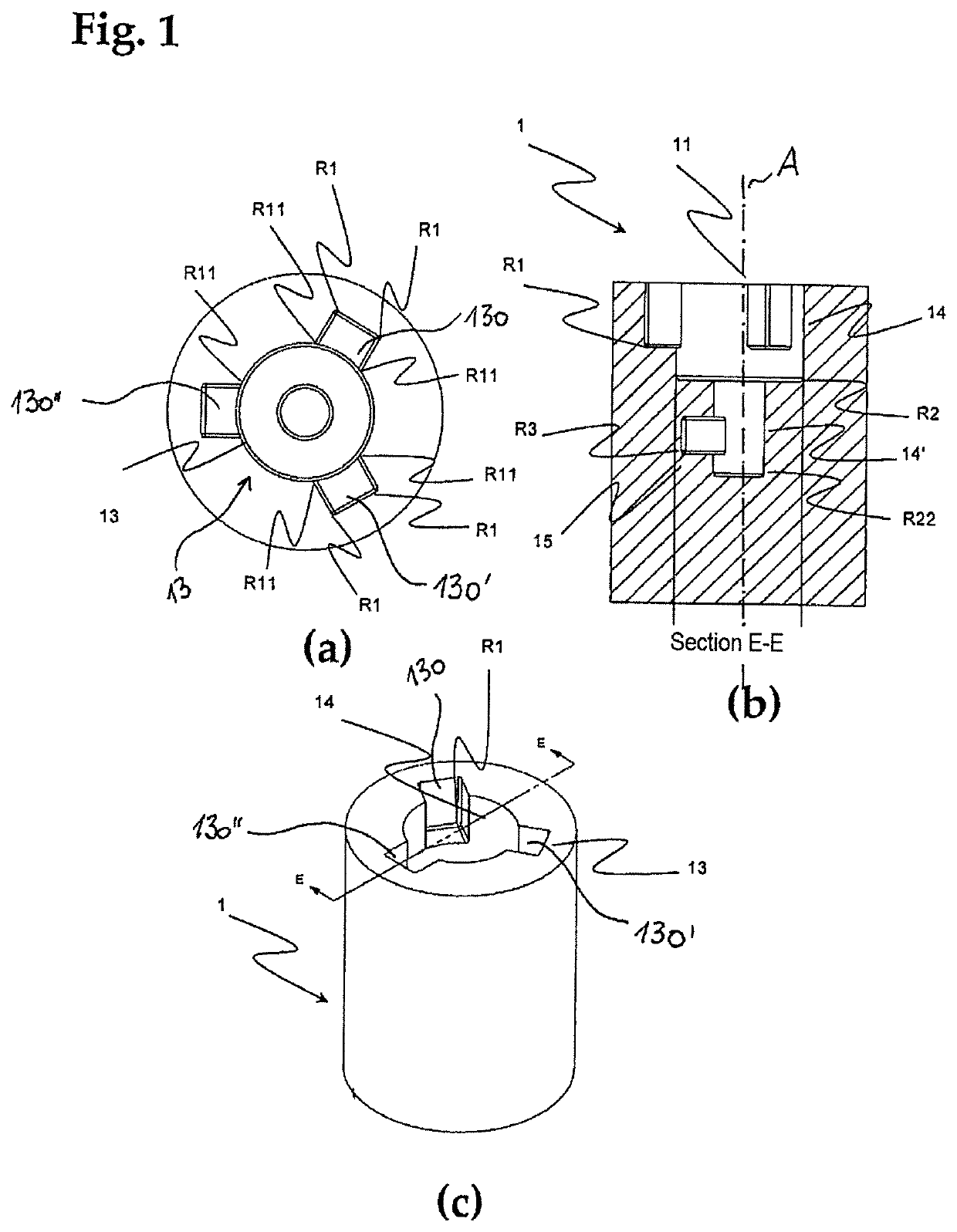
[0063]The production of the inventive dental prosthesis system, particularly the machining of the corner radii, is realized with the aid of an ultrashort pulse laser. In a preferred variation of the inventive method, the pulse duration of the ultrashort pulse laser amounts to 10 ps [picoseconds]. The laser used has an average output of 10 watt, a pulse frequency of 50 kHz-8.2 MHz and a wavelength of 1064 nm [nanometer]. In another preferred variation, the laser output amounts to 8 watt and the pulse frequency amounts to 100 kHz. An exemplary scanning speed of the laser lies at 100 mm / s.

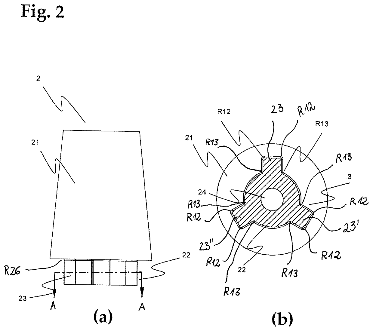
[0064]In another variation, the production of the inventive dental prosthesis system is realized with the aid of a full diamond milling cutter and / or drill that is fixed in a conventional CNC milling machine. In an exemplary variation, the drilling operation is carried out with a cutting speed of 20 (m / min) and an advance of 2 mm / min. The drill used has a diameter, for example, of 1.8 mm and a length ...


PUM

PropertyMeasurementUnit
corner radiiaaaaaaaaaa
corner radiusaaaaaaaaaa

Abstract

A dental prosthesis system includes at least one first and second dental prosthetic care part (1, 2) made of zirconium dioxide (ZrO2). Each of the two care parts has corner radii (R1, R11, R2, R22, R3, R26, R12, R13), and the corner radii (R1, R11, R2, R22, R3, R26, R12, R13) correspond to one another, wherein the first care part (1) is operatively connected to the second care part (2). At least one of the corner radii (R1, R11, R2, R22, R3) of the first dental prosthetic care part and / or the second dental prosthetic care part (R26, R12, R13) has a value of less than 0.1 mm, and the at least one corner radius (R1, R11, R2, R22, R3, R26, R12, R13) is produced by a material removal process using a laser method and / or by a machining process using a drill or a milling cutter made of full diamond.

Description

BACKGROUND OF THE INVENTIONField of the Invention[0001]The invention pertains to an at least two-part dental prosthesis system of zirconium dioxide with a first and a second dental prosthetic care part, wherein the corner radii of these care parts are very small corner radii. The invention furthermore pertains to a method for producing these care parts.Discussion of Related Art[0002]Three machining techniques for zirconium dioxide are known from the prior art for the production of dental prosthesis systems. Hard-machining of the already sintered base body by means of diamond grinding is carried out in order to produce the desired geometric shape of the implant and the associated parts such as abutments, screws and pins.[0003]In a second method for achieving the desired shape of the zirconium oxide body, it is machined in the form of a green body prior to the sintering operation, wherein this method is easier due to the lower hardness of the material. However, it was determined that ...

Claims


Application Information

Patent Timeline
Patent Type & Authority Patents(United States)
IPC IPC(8): A61C8/00A61C13/083A61L27/10
CPCA61C8/0012A61C8/0066A61C13/083A61L27/10A61C13/0004A61C13/0018A61C13/0022A61K6/818
Inventor BOLLETER, PHILIPWETTSTEIN, PASCALWARHANEK, MAXIMILIAN
Owner DENTALPOINT
Why Eureka
Try Eureka