
Dynamic touch quarantine frames

a dynamic touch and quarantine frame technology, applied in the field of improved touch determination, can solve the problems of system missing real but light touches from users, occurrence of false positive or ghost touches, and difficulty in detection of real touches, so as to reduce latency, add a degree of signal noise, and reduce the effect of nois

Active Publication Date: 2021-11-23
FLATFROG LAB
View PDF838 Cites 3 Cited by
  • Summary
  • Abstract
  • Description
  • Claims
  • Application Information

AI Technical Summary

Benefits of technology

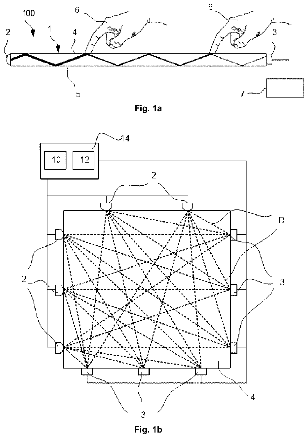
[0012]A method of detecting touches is needed which operates without the use of a high signal to noise threshold or an expensive low-noise system. The method should be able to balance the need to have a low touch threshold for light touches without compromising on the frequency of false positive touches due to noise. Finally, the method should ensure that the touch latency (i.e. the time between the initial detection of a touch trace and the output of a confirmed touch) is always as low as possible.
[0023]In one embodiment of the invention, one or more characteristics may comprise a noise value, wherein the noise value corresponds to a determined background and / or local electrical and / or optical noise. In a particular embodiment, the first number of frames is increased in proportion to the noise value. This advantageously allows the number of quarantine frames to be increased when either general background noise is increased or when noise local to the trace touch is determined to be above a threshold value.

Problems solved by technology

One potential problem with any type of touch screen system is the occurrence of ‘false-positive’ or ‘ghost’ touches.
However, this makes the detection of real touches more difficult and can lead to the system missing real but light touches from the user.
The alternative is to design the system to have low noise but this can require expensive materials and manufacturing techniques to implement.
One problem with this technique is that it can significantly increase latency of a detected real touch.

Method used


Image

  • Dynamic touch quarantine frames
  • Dynamic touch quarantine frames
  • Dynamic touch quarantine frames

Examples


Embodiment Construction

Terms

[0046]Before describing embodiments of the invention, a few definitions will be given.

[0047]A “touch object” or “touching object” is a physical object that touches, or is brought in sufficient proximity to, a touch surface so as to be detected by one or more sensors in the touch system. The physical object may be animate or inanimate.

[0048]An “interaction” occurs when the touch object affects a parameter measured by the sensor.

[0049]An “interaction strength” is a relative or absolute measure of the degree of interaction. The “interaction strength” may be represented as an “attenuation”.

[0050]An “interaction map” or “interaction pattern” is a two-dimensional (2D) distribution of interaction strength across the touch surface, or a portion thereof. If the interaction is presented as attenuation, the interaction map / pattern is also denoted an “attenuation map” or “attenuation pattern”.

[0051]A “touch” denotes a point of interaction as seen in the interaction pattern.

[0052]A “frame” ...


PUM


Abstract

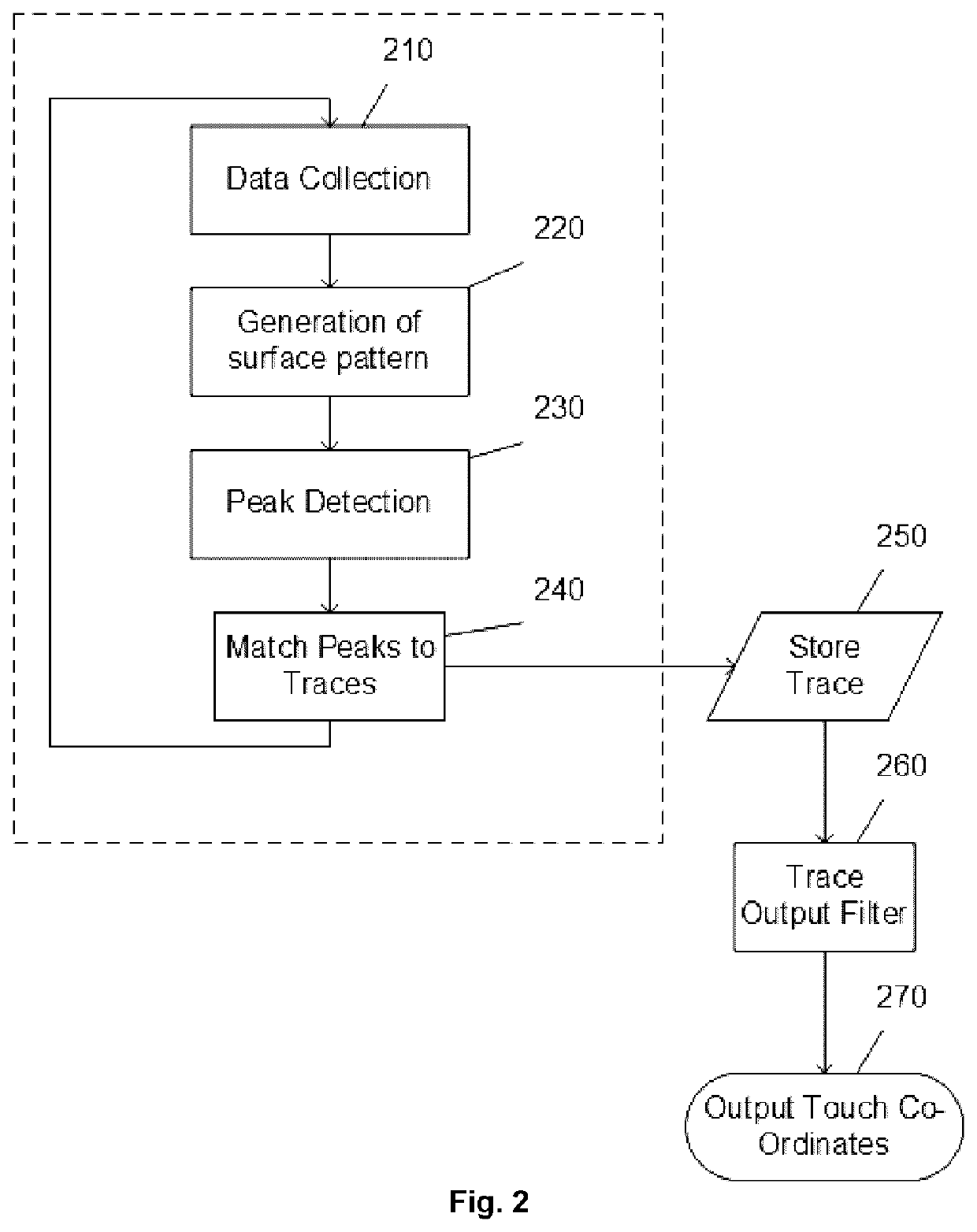
A touch system is described having a method of determining touch of one or more objects on a touch surface of a touch-sensitive apparatus, wherein the method operates in a time sequence of frames, each frame comprising the steps of: for a current frame, processing an output signal of the touch sensitive apparatus to generate one or more touch traces, each touch trace having one or more characteristics; and outputting a confirmed touch signal for each touch trace having a touch trace matching at least one of said one or more characteristics in a first number of frames preceding the current frame, wherein the first number of frames is determined in dependence on said one or more characteristics.

Description

CROSS-REFERENCE TO RELATED APPLICATIONS[0001]This application claims the benefit and priority to and is a U.S. National Phase of PCT International Application No. PCT / SE2016 / 050053, filed on Jan. 28, 2016. This application claims the benefit and priority to Swedish Patent Application No. 1550085-3, filed Jan. 28, 2015. The disclosure of the above-referenced applications are hereby expressly incorporated by reference in their entirety.TECHNICAL FIELD[0002]The present invention generally relates to improved touch determination on touch surfaces of optical touch-sensing systems, and in particular in relation to FTIR-based (frustrated total internal reflection) touch systems.BACKGROUND ARTTouch Sensing Systems[0003]Touch-sensing systems (“touch systems”) are in widespread use in a variety of applications. Typically, the touch systems are actuated by a touching object such as a finger or stylus, either in direct contact, or through proximity (i.e. without contact), with a touch surface. ...

Claims


Application Information

Patent Timeline
Patent Type & Authority Patents(United States)
IPC IPC(8): G06F3/042G06F3/0488G06F3/041G06F3/04883
CPCG06F3/0421G06F3/0428G06F3/04186G06F3/04883G06F2203/04109
Inventor OHLSSON, NICKLASANDREASSON, MARKUSCHRISTIANSSON, TOMASBJÖRKLUND, ANDREASWALLANDER, MATS PETER
Owner FLATFROG LAB
Learn More