Vehicle position correction method and vehicle position correction device for drive-assisted vehicle

Active Publication Date: 2021-11-09
NISSAN MOTOR CO LTD
View PDF74 Cites 2 Cited by
  • Summary
  • Abstract
  • Description
  • Claims
  • Application Information

AI Technical Summary

Benefits of technology

The patent discusses a method for correcting a vehicle's route by moving sideways, instead of just adjusting its position. This allows drivers to choose between smoothness and non-departure based on their situation. The method helps to make the vehicle's behavior more comfortable for the driver.

Problems solved by technology

However, with this conventional device, the self-position of the host vehicle is corrected, and thus any correction applied must take into account all modules that use self-position information, and correction that focuses on vehicle behavior cannot be performed.

Method used


Image

  • Vehicle position correction method and vehicle position correction device for drive-assisted vehicle
  • Vehicle position correction method and vehicle position correction device for drive-assisted vehicle
  • Vehicle position correction method and vehicle position correction device for drive-assisted vehicle

Examples


first embodiment

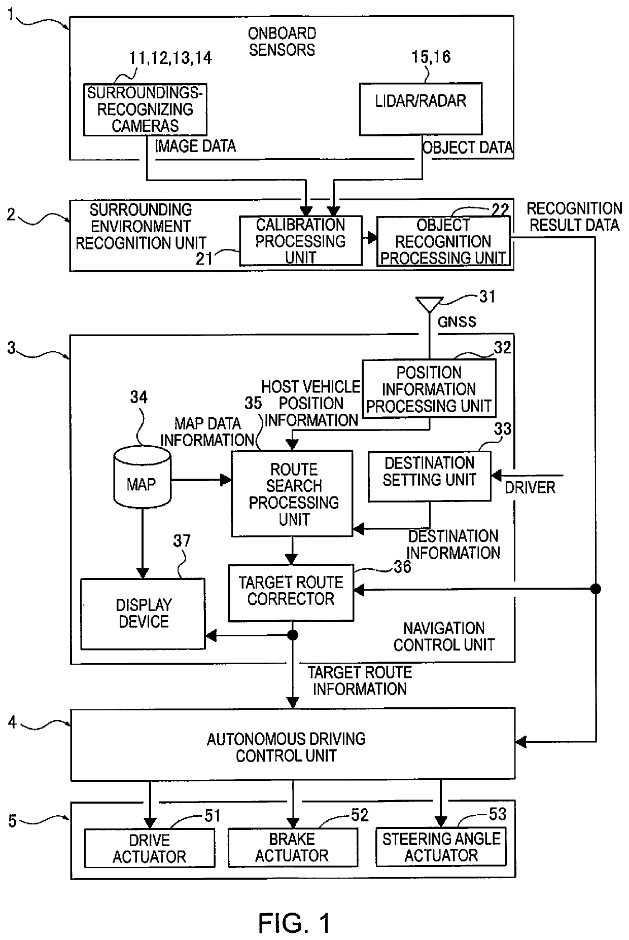
[0020]First, the configuration will be described. The method and device for generating a target method and device for correcting a position error of the first embodiment are applied to an autonomous vehicle (one example of a drive-assisted vehicle) in which steering / drive / braking are automatically controlled according to an autonomous driving mode selection using target route information generated by a navigation control unit. The configuration of the first embodiment will be described under the headings “Overall system configuration,”“Detailed configuration of navigation control unit,” and “Overall configuration of target route corrector,”“Detailed configuration of road boundary information consolidation unit,” and “Detailed configuration of lateral correction amount calculation unit.”

[0021]Overall System Configuration

[0022]FIG. 1 illustrates an autonomous driving control system to which the method and device for correcting a position error of the first embodiment have been applied...


PUM


Abstract

A vehicle position correction device corrects a position error of an host vehicle provided with a navigation control unit that includes a target route corrector that corrects a target route. The target route corrector detects a lane boundary of a lane in which the host vehicle travels. The target route corrector compares positional relationships between a detect lane boundary and a target route on a map, and calculates a lateral correction amount for the target route in situations where the target route is within a prescribed distance of the lane boundary, or in situations where the target route is on an opposite side of the lane boundary to the host vehicle. Upon calculating the lateral correction amount, the target route corrector moves the target route sideways in a lateral direction by the lateral correction amount to correct the target route.

Description

CROSS-REFERENCE TO RELATED APPLICATIONS[0001]This application is a U.S. national stage application of International Application No. PCT / JP2017 / 031166, filed on Aug. 30, 2017.BACKGROUNDTechnical Field[0002]The present disclosure relates to a method and device for correcting a position error of a drive-assisted vehicle, with which error arising between a position of a host vehicle and a target route during drive-assisted travel is corrected.Background Information[0003]Conventionally, in situations where a steering override is detected and then the end of the steering override is detected during control of autonomous driving or other travel, the driver is presumed to have returned the host vehicle to a travel route set in the center of white lines. One known device for estimating a position of a host vehicle assumes that the position at which the steering override ends is inside a lane, and corrects the self-position of the host vehicle by an amount of GPS / map divergence (e.g., see Jap...

Claims


Application Information

Patent Timeline
IPC IPC(8): B60W30/12B60W40/105B60W50/02B60W50/08G06K9/00G06V10/98
CPCB60W30/12B60W40/105B60W50/0225B60W50/08G06K9/00798B60W2552/53G08G1/09G01C21/3602G01C21/3407G01C21/3658B60W2556/40B60W2520/10B60W2720/12B60W30/18163B60W2540/20G06V20/588G06V10/98B60W30/10
Inventor FUKUSHIGE, TAKASHITANGE, SATOSHI
Owner NISSAN MOTOR CO LTD
Why Eureka
Try Eureka