Screening apparatus for optical fiber and screening method for optical fiber

a screening apparatus and optical fiber technology, applied in the testing of optical apparatus, instruments, manufacturing tools, etc., can solve the problems of low strength part of optical fiber that cannot withstand the applied tension, optical fiber may be broken and disconnected at the low strength part, and normal optical fiber may be damaged, so as to prevent the occurrence of fiber strikes on the side of feeding bobbins. , the effect of suppressing the strik

Active Publication Date: 2021-10-12
FURUKAWA ELECTRIC CO LTD
View PDF12 Cites 0 Cited by
  • Summary
  • Abstract
  • Description
  • Claims
  • Application Information

AI Technical Summary

Benefits of technology

[0016]According to the present invention, occurrence of a fiber-strike on the side of a feeding bobbin can be suppressed or prevented regardless of the weight of the feeding bobbin.

Problems solved by technology

In a screening test of an optical fiber, a low strength part of an optical fiber may fail to withstand the applied tension, and the optical fiber may be broken and disconnected at the low strength part.
When an optical fiber is disconnected in such a way, the end of the cut optical fiber may strike a normal optical fiber, and as a result, the normal optical fiber may be damaged.
In any of the above cases, a fiber-strike causes a problem of damaging a normal optical fiber or causing a normal optical fiber to deteriorate.
Thus, occurrence of a fiber-strike results in a high likelihood of an optical fiber being damaged.
Further, when a screening test is performed while an optical fiber is caused to continuously travel at a high speed, the traveling distance of the broken end of the optical fiber from the time when disconnection occurs to the time when rotation of the winding bobbin actually stops tends to be longer.
A longer traveling distance of the broken end causes a problem of a higher occurrence frequency of fiber-strike.

Method used


Image

  • Screening apparatus for optical fiber and screening method for optical fiber
  • Screening apparatus for optical fiber and screening method for optical fiber
  • Screening apparatus for optical fiber and screening method for optical fiber

Examples


first embodiment

[0025]A screening apparatus for an optical fiber and a screening method for an optical fiber according to a first embodiment of the present invention will be described by using FIG. 1 to FIG. 7.

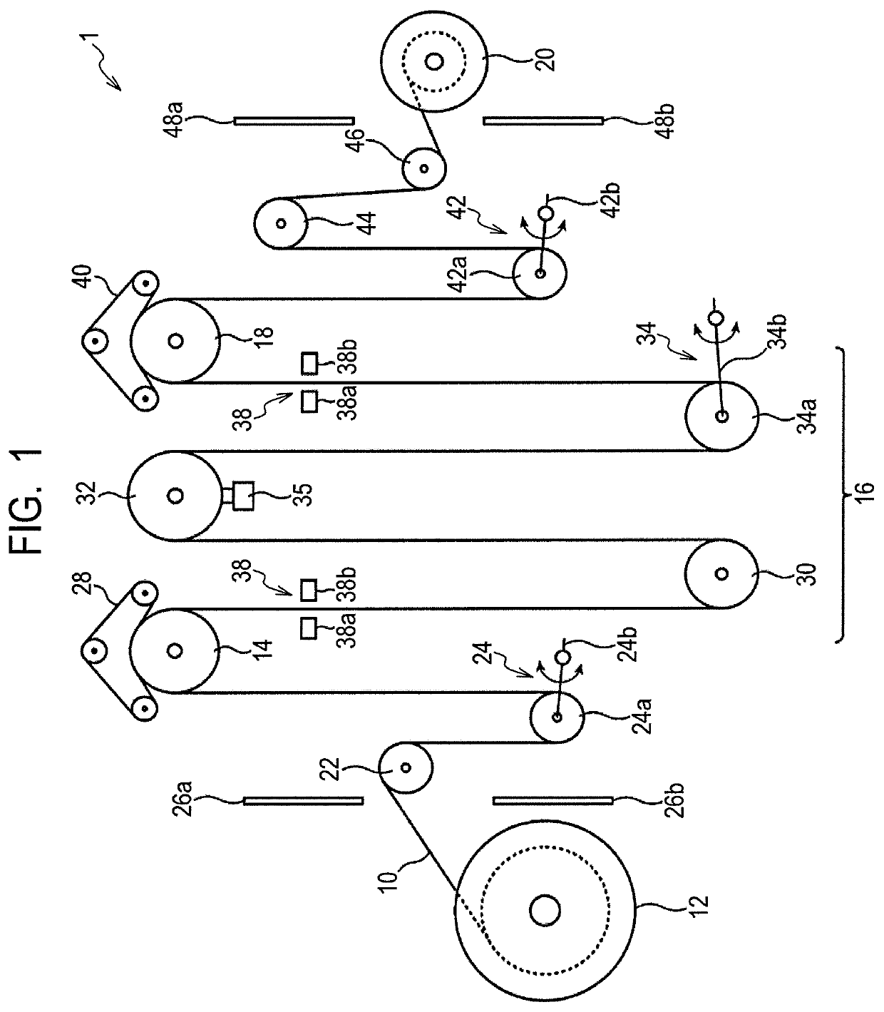
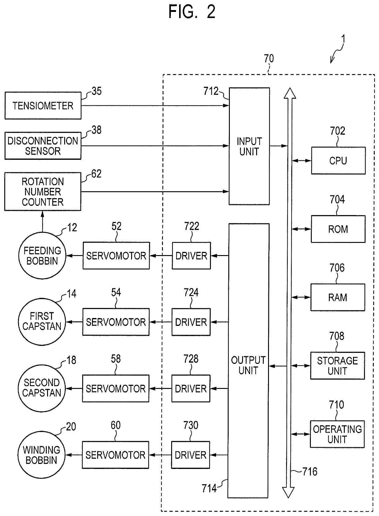
[0026]First, a configuration of the screening apparatus for an optical fiber according to the present embodiment will be described by using FIG. 1 and FIG. 2. FIG. 1 is a schematic diagram illustrating a screening apparatus for an optical fiber according to the present embodiment. FIG. 2 is a block diagram illustrating the screening apparatus for an optical fiber according to the present embodiment.

[0027]The screening apparatus for an optical fiber according to the present embodiment is an apparatus that performs a screening test for testing a tensile strength performance of an optical fiber. As illustrated in FIG. 1, a screening apparatus 1 for an optical fiber according to the present embodiment has a feeding bobbin 12, a first capstan 14, a screening unit 16, a second capstan 18, and a win...

second embodiment

[0141]A screening apparatus for an optical fiber and a screening method for an optical fiber according to a second embodiment for the present invention will be described by using FIG. 8. FIG. 8 is a block diagram illustrating the screening apparatus for an optical fiber according to the present embodiment. Note that the same components as those in the screening apparatus for an optical fiber and the screening method for an optical fiber according to the first embodiment described above are labeled with the same reference numerals, and the description thereof will be omitted or simplified.

[0142]While the case where the deceleration rate of the feeding bobbin 12 is calculated based on the rotation number of the feeding bobbin 12 measured by the rotation number counter 62 has been described in the first embodiment described above, the deceleration rate of the feeding bobbin 12 can be calculated based on other measurement values.

[0143]The basic configuration of the screening apparatus f...

modified embodiment

[0151]The present invention is not limited to the embodiments described above, and various modifications are possible.

[0152]For example, while the apparatus configuration having a predetermined number of pulleys and dancers illustrated in FIG. 1 has been described as an example for the screening apparatus 1 in the above embodiments, the number of pulleys and the number of dancers are not limited to the case illustrated in FIG. 1. The number of pulleys and the number of dancers can be changed as appropriate.

[0153]Further, in the above embodiments, the case where the servomotors 52, 54, 58, and 60 are used as motors that rotary-drive the feeding bobbin 12, the first capstan 14, the second capstan 18, and the winding bobbin 20 has been described as an example. However, the motors that rotary-drive the feeding bobbin 12, the first capstan 14, the second capstan 18, and the winding bobbin 20 are not limited to a servomotor, and various motors can be used.

[0154]Further, while the remainin...


PUM

PropertyMeasurementUnit
tensionaaaaaaaaaa
weightaaaaaaaaaa
strengthaaaaaaaaaa

Abstract

Provided is a screening apparatus or the like of an optical fiber that can suppress or prevent occurrence of a fiber-strike on the side of a feeding bobbin regardless of the weight of the feeding bobbin. An embodiment has a feeding bobbin 12 that feeds out an optical fiber 10; a screening unit 16 that applies a tension to the optical fiber 10 fed out from the feeding bobbin 12; a first capstan 14 that feeds the optical fiber 10 into the screening unit 16; a winding bobbin 20 that winds the optical fiber 10 to which the tension is applied by the screening unit 16; and a control unit 70 that, when disconnection of the optical fiber 10 occurs due to the tension applied by the screening unit 16, controls the feeding bobbin 12 and the first capstan 14 so as to stop rotation of the feeding bobbin 12 and rotation of the first capstan 14 and sets a deceleration rate of the first capstan 14 in accordance with a deceleration rate of the feeding bobbin 12.

Description

CROSS-REFERENCE TO RELATED APPLICATIONS[0001]This application is a continuation application of International Application No. PCT / JP2017 / 010911, filed Mar. 17, 2017, which claims the benefit of Japanese Patent Application No. 2016-055908, filed Mar. 18, 2016. The contents of the aforementioned applications are incorporated herein by reference in their entireties.TECHNICAL FIELD[0002]The present invention relates to a screening apparatus for an optical fiber and a screening method for an optical fiber.BACKGROUND ART[0003]When an optical fiber has a low strength part where the strength is low due to a flaw or the like, disconnection may occur for the low strength part. Accordingly, a screening test is performed on a drawn optical fiber by applying a predetermined tension to test the tensile strength performance thereof. A screening test may be continuously performed directly on the optical fiber drawn by a manufacturing line by using a screening apparatus directly connected to a manufa...

Claims


Application Information

Patent Timeline
Patent Type & Authority Patents(United States)
IPC IPC(8): G01M11/08G01M11/00G02B6/02B65H63/00G01N3/00G02B6/44C03B37/12B65H63/024
CPCG01M11/088B65H63/00B65H63/024C03B37/12G01M11/00G01N3/00G02B6/02G02B6/4458B65H2701/32
Inventor SUZUKI, TAKASHI
Owner FURUKAWA ELECTRIC CO LTD
Why Eureka
Try Eureka