Bearing screw transferring apparatus

a technology of bearing screw and transfer device, which is applied in the direction of gearing, shaft and bearing, linear bearing, etc., can solve the problems of not being commercialized, affecting the efficiency of conversion, so as to achieve smooth power conversion, easy adjustment of preload, and easy adjustment

Active Publication Date: 2021-09-07
WINNER
View PDF26 Cites 0 Cited by
  • Summary
  • Abstract
  • Description
  • Claims
  • Application Information

AI Technical Summary

Benefits of technology

[0022]According to the present disclosure having the above-described configuration, the operating plate disposed on the upper portion of the screw shaft is used as a means for supporting the driving bearings, instead of a cylinder or a rod arranged in a cylindrical shape, and the first driving bearings and the second driving bearings are coupled to the operating plate symmetrically in the forward and backward directions to be inclined, and each driving bearing is installed to run along only one surface of two surfaces of the screw groove of the screw shaft. Therefore, each of the driving bearings is not influenced by a preload of the other driving bearing, and the preload is independently maintained, such that contact between the surface of the outer ring of the driving bearing and the screw groove of the screw shaft can be constantly maintained during operation. In addition, since all of the outer rings of the driving bearings are exposed in the forward and backward directions of the operating plate, a preload between the surface of the outer ring and the screw groove of the screw shaft can be easily adjusted when the preload is out of an appropriate range, as well as when the device is initially assembled. In particular, since the preload adjustment bolts are secured into the penetrating taps of the upward bending wings of the operating plate to adjust a preload, it is very easy to adjust the preload. Once the preload is appropriately adjusted, factors causing a change in the preload are all absorbed within a predetermined range by the first elastic plate and the second elastic plate during use of the bearing screw transfer device. Therefore, the preload between the surface of the outer ring of the bearing and the screw groove of the screw shaft is maintained with a predetermined range and smooth power conversion is achieved.
[0023]In addition, since the weight of the operating plate and the weight of the carrier or operating block or the weight of the load loaded on the operating plate are distributed to the guide rails through the double bending wings of the operating plate and the guide bearing, a load exerted to the screw shaft can be greatly reduced, and accordingly, deflection of the screw shaft or shaking of the screw shaft can be prevented. Stable and secure power conversion can be achieved by minimizing a change in the preload between the screw shaft and the outer ring of the driving bearing during operation. In particular, the guide bearings are coupled to the self-adjustment plates turning around the rotary shafts. Therefore, even when parallel between the screw shaft and the guide rails is temporarily broken due to displacement of the screw shaft and pitching occurs during operation, a great change in the preload resulting therefrom is mostly absorbed by the rotation of the self-adjustment plates. Accordingly, the preload between the screw shaft and the outer ring of the driving bearing is maintained with a predetermined range, and stable power conversion is achieved.
[0024]In addition, one pair of support bearings are installed under the screw shaft, and are provided to be subjected to elastic force in the direction toward the screw shaft. Therefore, deflection of the screw shaft can be prevented, and when yawing of the screw shaft temporarily occurs during operation, the screw shaft is automatically restored to its original position, such that the preload between the screw shaft and the outer ring of the driving bearing is maintained within a predetermined range, and stable power conversion can be achieved.

Problems solved by technology

The above-described related-art bearing screw transfer devices were actually manufactured and underwent many tests, but were not commercialized due to the following problems.
If the preload between the screw shaft and the bearing is excessively high, a great load may be exerted to the driving motor of the screw shaft and efficiency of conversion may greatly deteriorate.
However, the related-art bearing screw transfer devices have difficulty in adjusting the preload of each bearing appropriately before or after driving, and there is a problem that the preload is abruptly changed during operation.
Accordingly, it is very difficult to appropriately adjust preloads of all bearings.
In particular, if two or more bearings are installed on the same continuous surface on one side of the screw groove of the screw shaft, it is extremely difficult to appropriately adjust preloads of the bearings.
Accordingly, in the related-art bearing screw transfer device, only one or two bearings may contribute to transmission of power, and the other bearings may remain idle.
However, in the state in which the cylinder is assembled to the screw shaft, it is very difficult to precisely adjust the preload because the screw groove of the screw shaft is not exposed to the outside.
This means that it is very difficult to adjust the preload during use of the related-art bearing screw transfer device even if the preload is not appropriate and power conversion and transmission are not smoothly performed.
This is because it is very difficult to continuously and constantly maintain contact between the surface of the outer ring of the bearing and the screw groove of the screw shaft.
Although there are various reasons for change of the preload during operation, the biggest reason is temporary deformation of the screw shaft such as deflection of the screw shaft or shaking of the screw shaft.
A bearing temporarily released from the contact with the screw shaft does not contribute to transmission of power, and a bearing contacting the screw shaft under great pressure inappropriately may degrade efficiency of power transmission.

Method used


Image

  • Bearing screw transferring apparatus
  • Bearing screw transferring apparatus
  • Bearing screw transferring apparatus

Examples


Embodiment Construction

[0033]Hereinafter, specific embodiments of a bearing screw transfer device according to the present disclosure will be described in detail with reference to the accompanying drawings.

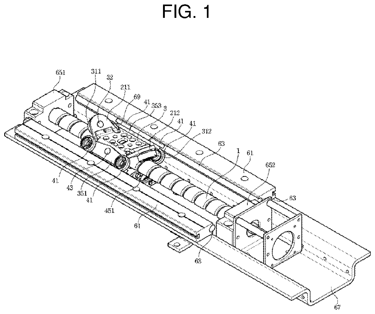
[0034]The bearing screw transfer device according to the present disclosure includes one pair of driving bearings 311, 312 which run along a screw groove of a screw shaft 1 to convert a rotational force of the screw shaft 1 into a translational force.

[0035]As shown in FIG. 1, the screw shaft 1 may be installed to have a journal supported by two shaft supporters 651, 652 which are spaced apart from each other inside a channel type frame 67. Although not shown, a driving means such as a motor, a geared motor, a geared motor may be coupled to one end of the screw shaft 1 by means of a shaft.

[0036]Both side ends of the channel type frame 67 may be extended in a horizontal direction and guide blocks 61 may be installed on the extended surfaces along a channel longitudinal direction as long as a screw forming...


PUM


Abstract

A bearing screw transfer device which converts a rotational motion of a screw shaft into a linear motion by the medium of a bearing is disclosed. The bearing screw transfer device has a first driving bearing and a second bearing which run along a screw groove of a rotating screw shaft, thereby converting a rotational force of the screw shaft into a translational force of an operating plate disposed on an upper portion of the screw shaft, wherein a two-surface screw groove is formed on the screw shaft, and an outer ring of the first driving bearing runs in contact with one surface of the two-surface screw groove, and an outer ring of the second driving bearing runs in contact with the other surface of the screw groove.

Description

TECHNICAL FIELD[0001]The present disclosure relates to a bearing screw transfer device, and more particularly, to a bearing screw transfer device which converts a rotational motion of a screw shaft into a linear motion by the medium of a bearing.BACKGROUND ART[0002]The inventor(s) of the present disclosure filed an application for a patent regarding a screw transfer device using a bearing, under Korean Patent Application No. 10-2005-0126950, and received registration of Korean Patent No. 10-0657657. Thereafter, the invention has been developed and has been disclosed in Korean Patent Laid-Open Publication No. 10-2007-0059976, Korean Patent Registration No. 10-0828235, Korean Patent Registration No. 10-0883628, Korean Patent Registration No. 10-0919909, Korean Patent Registration No. 10-0860720, Korean Patent Registration No. 10-1150340, Korean Patent Registration No. 10-1083739, Korean Patent Registration No. 10-1084376, Korean Patent Registration No. 10-1039623, Korean Patent Laid-O...

Claims


Application Information

Patent Timeline
Patent Type & Authority Patents(United States)
IPC IPC(8): F16H25/20F16H25/24
CPCF16H25/20F16H25/24F16H2025/2081F16H2025/2436F16C29/04F16H2025/204F16H25/2261F16H25/22
Inventor SONG, CHEUN BOK
Owner WINNER
Why Eureka
Try Eureka