
Well tool assembly

a technology for drilling tools and drilling holes, applied in earth-moving drilling, surveying, construction, etc., can solve the problems of pressing the setting tool upward, and destroying the setting tool, so as to facilitate the lowering of the plugging tool

Active Publication Date: 2021-06-01
INTERWELL NORWAY AS
View PDF12 Cites 2 Cited by
  • Summary
  • Abstract
  • Description
  • Claims
  • Application Information

AI Technical Summary

Benefits of technology

[0008]an outer actuator having a outer connection interface in its lower end, where the setting tool is configured to provide relative axial motion between the inner and outer actuators, thereby causing the plugging tool to be moved between its radially retracted state and its radially expanded state;where the plugging tool comprises:
[0022]In one aspect, the lower section of the lowermost device is comprising a nose section of the plugging tool, where the lose section is providing a closing of a bore through the inner mandrel device. In an alternative embodiment, the bore is a through bore. Also here, a nose section can be provided to ease the lowering of the plugging tool into the well, where the bore through the mandrel device is continued through the nose section.

Problems solved by technology

The operation of determining the location of such a zone is often time-consuming.
However, when set, the differential pressure over a sealing element of such a plugging tool may be as high as 70 000 lbf (corresponding to a weight of 31 tons), which will press the setting tool upwardly and destroy the setting tool.
The disadvantage with the ratchet mechanism is that, when set, it is cumbersome to reset again, as this typically requires a disassembly of the tool.
Hence, it is often the resetting of the ratchet mechanism which is causing the number of runs needed during the abovementioned operations.

Method used


Image

  • Well tool assembly
  • Well tool assembly
  • Well tool assembly

Examples


Embodiment Construction

[0030]Embodiments of the invention will be described in detail below with reference to the enclosed drawings, where:

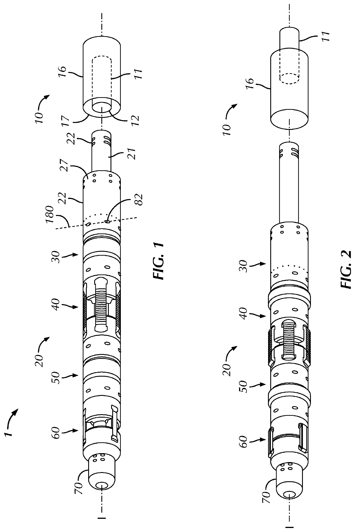
[0031]FIG. 1 illustrates a perspective view of the well tool assembly in a run state, where the setting tool is illustrated schematically;

[0032]FIG. 2 illustrates a perspective view of the well tool assembly in the set state;

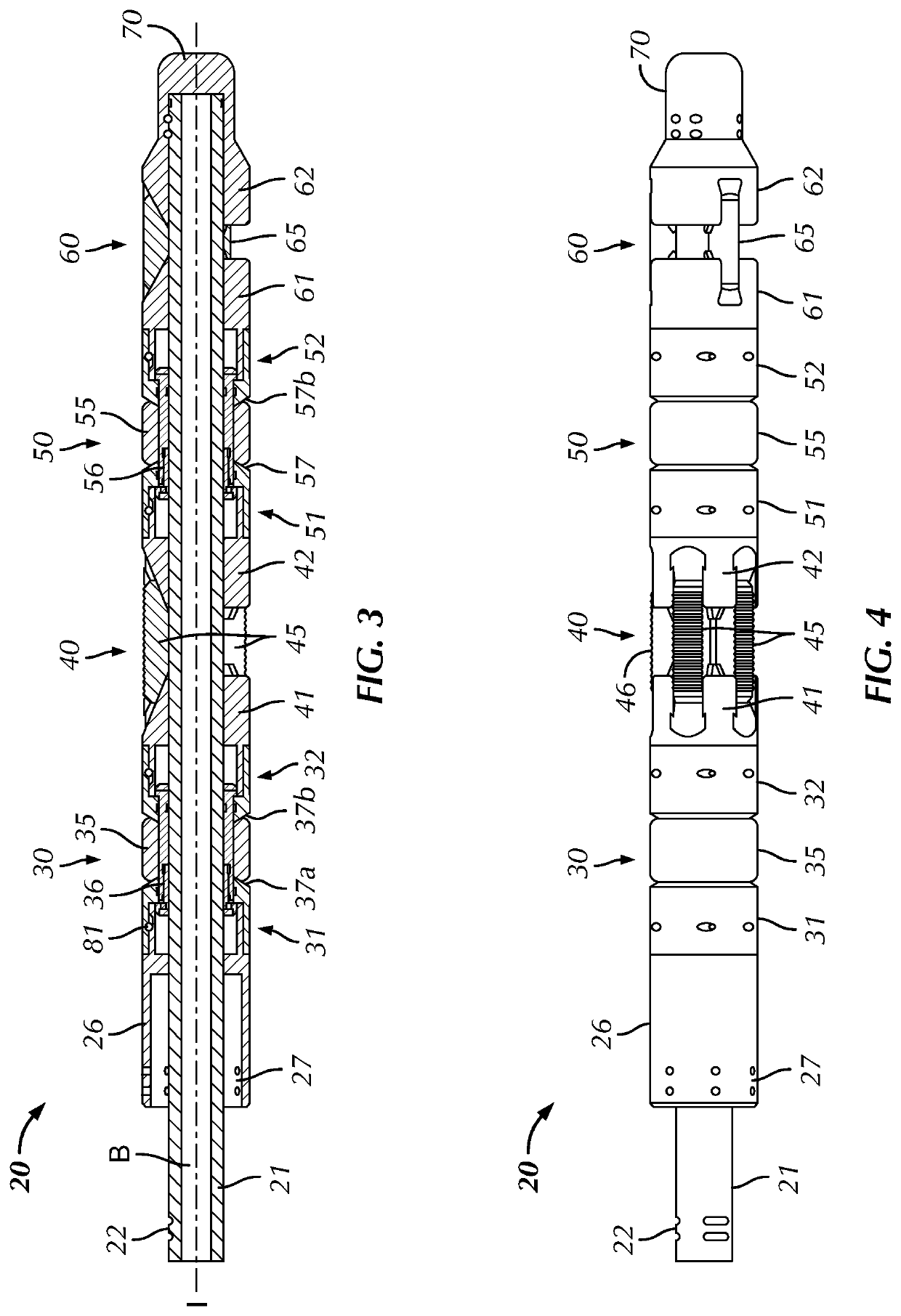
[0033]FIG. 3 illustrates a cross sectional view of the plugging tool in its run state;

[0034]FIG. 4 illustrates a side view of the plugging tool in its run state;

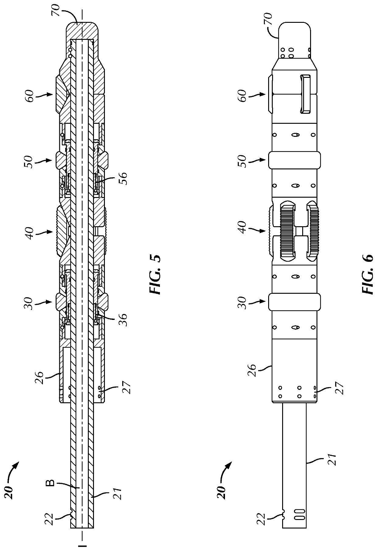
[0035]FIG. 5 illustrates a cross sectional view of the plugging tool in its set state;

[0036]FIG. 6 illustrates a side view of the plugging tool in its set state;

[0037]FIGS. 7 and 8 illustrates the well tool assembly in a well pipe in its run and set states respectively;

[0038]FIG. 9 illustrates an alternative embodiment where the inner mandrel device comprises a through bore;

[0039]FIG. 10 illustrates an alternative embodiment where the centralizing device is provided above the upper sealing ...


PUM


Abstract

The invention relates to a well tool assembly (1) comprising a setting tool (10) and a plugging tool (20). The plugging tool (20) comprises:an inner mandrel device (21) and an outer housing device (26), an upper sealing device (30), a slips device (40), a lower sealing device (50) and a centralizing device (60) connected to each other in an axial direction outside of the mandrel device 21. The slips device (40) is provided axially between the upper and lower sealing devices (30, 50). The centralizing device (60) is provided below the lower sealing device (50) or above the upper sealing device (30). When the centralizing device (60) is provided below the lower sealing device (50), the upper sealing device (30), the slips device (40), the lower sealing device (50) and the upper section (61) of the centralizing device (60) are axially displaceable downwardly and upwardly in relation to the mandrel device (21) and the upper section (31) of the upper sealing device (30) is connected to the outer housing device (26) and the lower section (62) of the centralizing device (60) is fixed to the inner mandrel device (21). When the centralizing device (60) is provided above the upper sealing device (30), the centralizing device (60), the upper sealing device (30), the slips device (40) and the upper section (51) of the lower sealing device (50) are axially displaceable downwardly and upwardly in relation to the mandrel device (21) and the upper section (61) of the centralizing device (60) is connected to the outer housing device (26) and the lower section (52) of the lower sealing device (50) is fixed to the inner mandrel device (21).

Description

FIELD OF THE INVENTION[0001]The present invention relates to a well tool assembly comprising a setting tool and a plugging tool. The well tool assembly is used for pressure testing of a well. The present invention also relates to a method for pressure testing a well. In particular, the well tool assembly and method is used for pressure testing of different zones in the well.BACKGROUND OF THE INVENTION[0002]During operations in hydrocarbon producing wells, there is a need to test different zones in the well. In one situation, one zone in the well may be producing water instead of oil / gas. It is then necessary to determine the location of that water-producing zone and thereafter to isolate that water-producing zone of the well. The operation of determining the location of such a zone is often time-consuming. One common way of doing this is to lower and set a plugging tool at an initial location in the well. The setting tool is then retrieved to surface, whereafter the content of the w...

Claims


Application Information

Patent Timeline
Patent Type & Authority Patents(United States)
IPC IPC(8): E21B33/128E21B47/117E21B17/10E21B33/129E21B33/1295E21B47/06
CPCE21B33/1285E21B17/1014E21B33/1293E21B33/1295E21B47/117E21B47/06E21B33/128E21B33/129E21B23/06E21B33/12E21B33/1208
Inventor HIORTH, ESPEN
Owner INTERWELL NORWAY AS
Learn More