Container with touch control arrangement

a container and touch control technology, applied in the field of containers, can solve the problems of user needing to replace batteries, inability to maintain infrared sensors in an always-on standby mode to continuously, waste of electrical power of infrared sensors in standby mode, etc., and achieve the effect of simplifying and reasonable structure configuration of containers and being convenient to us

Active Publication Date: 2021-05-18
NINE STARS GRP U S A INC
View PDF2 Cites 1 Cited by
  • Summary
  • Abstract
  • Description
  • Claims
  • Application Information

AI Technical Summary

Benefits of technology

[0007]The invention is advantageous in that it provides a container, such as a trash container, with a touch control arrangement, wherein the structural configuration of the container is simplified and reasonable, and is easy to use.
[0008]According to the present invention, the foregoing and other objects and advantages are attained by a container comprises a container cover, a cover resilient element, a container body, a connecting unit, a speed adjustor such as a decelerator, an electric motor, a circuit board module, an inner supporting frame, an outer supporting frame, a touch control arrangement. The container cover is pivotally connected to the container body via the connecting unit, wherein the connecting unit is coupled at an outer side of the container body to pivotally connect to the container cover. In particular, the container cover has two cover axle slots and connecting unit has two connecting axle slots coaxially aligned with the cover axle slots, wherein an axle shaft is extended through the cover axle slot and the connecting axle slot to pivotally connect the container cover to the container body. The cover resilient element is connected at the axle shaft to bias against the container cover and the container body. The inner supporting frame and the outer supporting frame are mounted at the bottom of the container body, wherein a front opening cavity is formed in front of the inner supporting frame and the outer supporting frame. The container body has a notch aligned with the front opening cavity to form an accessing cavity, wherein the touch control arrangement is supported at the accessing cavity. In one embodiment, the cover resilient element is a coil spring and is arranged for applying a resilient force against the container cover with respect to the container body. In particular, the resilient force, i.e. the spring force, of the cover resilient element will compensate most of the weight of the container cover. As a result, the electric motor requires generating less power to pivotally lift up the container cover from the container body. In other words, the size of the electric motor as proportional to its power generation and the cost of the electric motor will be reduced, so as to prolong the service life span of the electric motor. Accordingly, the connecting unit, the speed adjustor, the electric motor, the circuit board module, and a battery are supported and installed at the outer side of the container body to maximize an interior storage cavity of the container body. In addition, the connecting unit, the speed adjustor, the electric motor, the circuit board module, and the battery are located at the rear side of the container body to keep the aesthetic appearance of the container body. The touch control arrangement is supported within the accessing cavity at the front bottom side of the container body to form an integrated body for keeping the aesthetic appearance of the container body. The touch control arrangement is electrically connected to the circuit board module to activate the electric motor and the speed adjustor, so as to pivotally lift up the container cover.
[0009]The container cover comprises a sector gear provided at a rear bottom portion thereof and at a position between the cover axle slots, wherein the sector gear is engaged with an output gear of the speed adjustor. The connecting axle slots are formed at an upper portion of the container body, wherein the connecting unit has a planner shape that lower portion thereof is coupled at the container body. Accordingly, an axis of the sector gear, a center of each of the cover axle slots, and a center of each of the connecting axle slots are coaxially aligned with each other to form a pivot axle channel, such that the axle shaft, which is preferably made of metal, is slidably coupled at the pivot axle channel to pivotally connect the container cover with the connecting unit. It is worth mentioning that the container cover, the sector gear, and the cover axle slots are integrally formed as a one piece member via mold injection. In other words, the sector gear is integrally extended from the container cover while the cover axle slots are integrally formed at the upper portion of the container cover when the container cover is formed via mold injection, so as to ensure the precise configuration of the sector gear and the cover axle slots with respect to the container cover and to reduce the manufacturing cost thereof. The output gear is directly engaged with the sector gear to enhance the gear efficiency and to minimize the mechanical wear out of the gear. Preferably, the axle shaft is made of metal to provide a high strength ability to prevent any distortion through the pivotal movement of the container cover. In addition, the cover resilient element is coupled at the axle shaft, wherein the cover resilient element has one end biasing against the connecting unit and another end biasing against the container cover for applying the resilient force against the container cover so as to compensate most of the weight of the container cover.
[0010]The connecting unit further comprises a battery compartment integrally formed therein via mold injection. Accordingly, the speed adjustor, the electric motor, the circuit board module are orderly mounted at the connecting unit from top to bottom thereof to form a power assembly, such that the electric motor is located between the speed adjustor and the circuit board module. The connecting unit is coupled at the rear upper side of the container body via screws. A unit casing is detachably coupled at the connecting unit to enclose the speed adjustor, the electric motor, the circuit board module. It is worth mentioning that speed adjustor, the electric motor, the circuit board module can be manufactured individually or separately for enhancing the mass production of the components and for reducing the costs thereof.
[0014]The holding unit is constructed to have the outer holding ring and the inner holding ring. The outer holding ring is sleeved to and encircled around a top opening of the container body while the inner holding ring is encircled within the outer holding ring. Accordingly, an opening edge portion of a plastic bag (trash bag) is held by the outer holding ring and the inner holding ring. In particularly, when the plastic bag is disposed in the container body, the inner holding ring is coupled at an inner side of the container body to hold the opening edge portion of the plastic bag between the inner side of the container body and the inner holding ring. Then, the opening edge portion of the plastic bag can be outwardly folded to overlap on an outer side of the container body, such that the outer holding ring is coupled at the outer side of the container body to hold the folded opening edge portion of the plastic bag between the outer side of the container body and the outer holding ring. Therefore, the container of the present invention does not require any inner container body to hold the plastic bag to further reduce the manufacturing cost of the container. Since the folded opening edge portion of the plastic bag is encircled and hidden within the outer holding ring, the plastic bag cannot be seen from the exterior of the container so as to keep the aesthetic appearance of the container.
[0016]The advantages of the present invention is that the structural configuration of the container is simplified and reasonable that the container requires less components and less complicated structural configuration comparing to the conventional container. The cost and the power consumption of the container are relatively low. The container is easy to use and is able to maintain the container cover the opening position.

Problems solved by technology

However, the major drawback of the induction actuated trash container is that the infrared sensor must be maintained in an always-on standby mode to continuously transmit the infrared signal.
As a result, it is a waste that the infrared sensor consumes relatively lots of electrical power in the standby mode.
In other words, the user may need to replace the battery for the induction actuated trash container frequently due to the energy hog of the infrared sensor.
In addition, the induction actuated trash container is misused that the container cover is accidentally opened up when the infrared sensor detects a pet passing in front of the infrared sensor.
Another type is an touch sensor trash container, wherein the conventional touch sensor trash container is unreliable.
It is inconvenient for the user to detach and re-attach the head unit to the container body every time when replacing the trash bag.
Furthermore, the control circuit will be polluted by the trashes and the connection between the micro switch and the control circuit will be damaged and oxidized, so as to cause an improper operation of the trash container.
On the other hand, the cost of the trash container will be relatively high to include the inner container.
However, the electronic components may be polluted by the trashes.
Without the inner container, the trash container require more container components for actuating the container cover, wherein the configuration or arrangement of the container components is unreliable and is complicated.
As a result, the trash bag cannot be held properly and the cost of the trash container will be higher comparing with the trash container having the inner container.

Method used


Image

  • Container with touch control arrangement
  • Container with touch control arrangement
  • Container with touch control arrangement

Examples


Embodiment Construction

[0033]The following description is disclosed to enable any person skilled in the art to make and use the present invention. Preferred embodiments are provided in the following description only as examples and modifications will be apparent to those skilled in the art. The general principles defined in the following description would be applied to other embodiments, alternatives, modifications, equivalents, and applications without departing from the spirit and scope of the present invention.

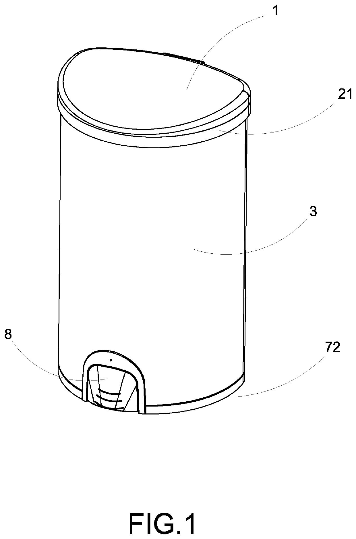
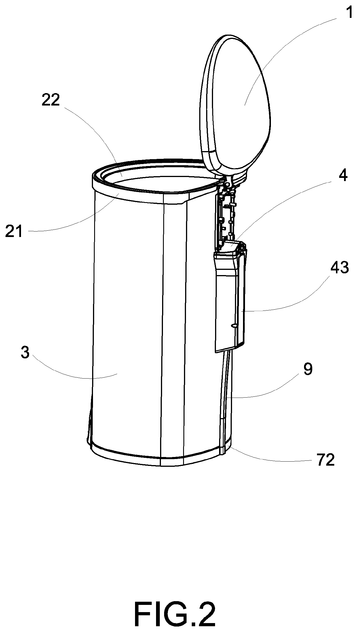
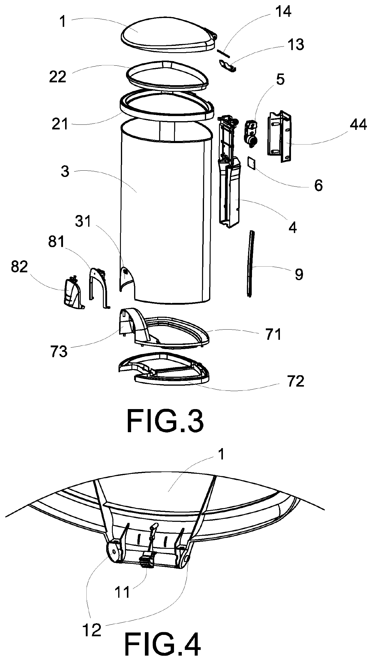
[0034]Referring to FIGS. 1-14 of the drawings, a container according to a preferred embodiment of the present invention is illustrated, wherein the container, which is embodied as a trash container as an example, comprises a container cover 1, a cover resilient element 13, a holding unit which comprises an outer holding ring 21 and an inner holding ring 22, a container body 3, a connecting unit 4, a speed adjustor 5 such as a decelerator, an electric motor 51, a circuit board module 6, an inner s...


PUM


Abstract

A container includes a container cover, a cover resilient element, a holding unit, a container body, a connecting unit, a speed adjustor, an electric motor, a circuit board module, an inner supporting frame, an outer supporting frame, a touch control arrangement, wherein the connecting unit is coupled at an outer side of the container body to pivotally connect the container cover with the container body. The cover resilient element is arranged for applying a resilient force against the container cover. The container body has an accessing cavity, wherein the touch control arrangement is supported at the accessing cavity. The structural configuration of the container is simplified that the container requires less components and less complicated structural configuration. The cost and the power consumption of the container are relatively low. The container is easy to use and is able to maintain the container cover the opening position.

Description

CROSS REFERENCE OF RELATED APPLICATION[0001]This is a non-provisional application that claims priority to international application number PCT / CN2017 / 076096, international filing date Mar. 9, 2017, which claims priority to Chinese application CN 201720069628.6, filing date Jan. 20, 2017, the entire contents of each of which are expressly incorporated herein by reference.NOTICE OF COPYRIGHT[0002]A portion of the disclosure of this patent document contains material which is subject to copyright protection. The copyright owner has no objection to any reproduction by anyone of the patent disclosure, as it appears in the United States Patent and Trademark Office patent files or records, but otherwise reserves all copyright rights whatsoever.BACKGROUND OF THE PRESENT INVENTIONField of Invention[0003]The present invention relates to containers, and more particularly to a container with a touch control arrangement.Description of Related Arts[0004]There are generally two types of automatic t...

Claims


Application Information

Patent Timeline
Patent Type & Authority Patents(United States)
IPC IPC(8): B65F1/16B65F1/06
CPCB65F1/1638B65F1/06B65F1/1646
Inventor WANG, XINCHEN, JIANGQUNYANG, XIUJINZHENG, HUIYANGLIN, ZHOU
Owner NINE STARS GRP U S A INC
Why Eureka
Try Eureka