Shielded fluoropolymer wire for high temperature skin effect trace heating

a fluoropolymer wire and trace heating technology, which is applied in the direction of heating element materials, heating element shapes, conductors, etc., can solve the problems of increased charge buildup between the two surfaces, protracted partial discharge, and breakage of insulation at the point of contact, so as to minimize the number of discreet circuits needed, the effect of increasing the voltag

Active Publication Date: 2021-05-11
NVENT SERVICES GMBH
View PDF26 Cites 0 Cited by
  • Summary
  • Abstract
  • Description
  • Claims
  • Application Information

AI Technical Summary

Benefits of technology

[0006]Embodiments of the invention overcome the aforementioned drawbacks by providing a heater cable that may be installed to heat long pipelines using as few discrete lengths of heater cable as possible, in order to maximize circuit lengths, which minimizes the number of discreet circuits needed for the pipeline. In particular, the invention provides a heater cable that can be rated at higher voltages while maintaining partial discharge at an acceptable level. The heater cable includes commonly-used materials, particularly electrical insulation materials, but is capable of withstanding a continuous applied voltage that exceeds the commonly applicable rated voltages of such materials without creating undesirable levels of partial discharge. The heater cable comprises a core conductor and an electrical insulation layer surrounding the core conductor. The heater cable further comprises an outer exposed semiconductive layer surrounding the electrical insulation layer. The semiconductive layer is in physical and electrical contact with an inner diameter of a ferromagnetic heat tube.
[0008]In one embodiment, the outer semiconductive layer has a resistivity whereby, when an alternating current is applied to the conductor at a voltage exceeding 5 kV up to about 10 kV or 14 kV (e.g., the outer semiconductive layer is over an insulating layer of silicone), partial discharge of the heater cable does not exceed 20 nanocoulombs. In another aspect, the outer semiconductive layer has a resistivity whereby, when an alternating current is applied to the conductor at a voltage between about 2.5 kV and about 5 kV or 7 kV (e.g., the outer semiconductive layer is over an insulating layer of perfluoroalkoxy polymer (PFA)), partial discharge of the heater cable does not exceed 1 nanocoulomb, and further may not exceed 10 picocoulombs. Additionally, in any aspect, no more than an insignificant portion of a return electric current, the return electric current flowing on the inner surface of the heat tube in opposite direction to the alternating current of the conductor, is diverted to the outer semiconductive layer, such that the loss by the heat tube of the insignificant portion does not affect heat output of the heat tube. The resistivity of the outer semiconductive layer can be between 10−1 and 105 ohm-cm inclusive, or more particularly between 5 and 1000 ohm-cm inclusive, and even more particularly between 5 and 50 ohm-cm inclusive. The outer semiconductive layer can be an extruded layer that is extruded onto the electrical insulation layer. Or, the outer semiconductive layer can be a semiconductive tape wrapped around the electrical insulation layer.
[0010]In another embodiment, the invention provides a heater cable for a skin effect heating system. The heater cable includes a core conductor, an electrical insulation layer surrounding the core conductor, and an outer semiconductive layer surrounding the electrical insulation layer, the outer semiconductive layer contacting an inner surface of a ferromagnetic heat tube such that the heater cable forms an electrical circuit with the heat tube and a power source applying an alternating current to the core conductor, the electrical circuit causing skin effect heating of the heat tube. The outer semiconductive layer reduces partial discharge of the heater cable when the alternating current is applied continuously to the core conductor at a voltage exceeding 3 kV, or more particularly 3.5 kV, or even more particularly 5 kV.
[0011]In one embodiment, for a cable having a silicone insulating layer, the outer semiconductive layer can have a resistivity that limits partial discharge of the heater cable to no greater than 20 nanocoulombs, or at or below 10 picocoulombs; the outer semiconductive layer can further prevent flow of a substantial portion of an electric current flowing on the inner surface of the heat tube into the outer semiconductive layer. The outer semiconductive layer can reduce partial discharge of the heater cable when the alternating current is applied continuously to the core conductor at a voltage of 10 kV to 14 kV, inclusive. In another embodiment, for a cable having a PFA insulating layer, the outer semiconductive layer can have a resistivity that limits partial discharge of the heater cable to at most 1 nanocoulomb, or more specifically at most 10 picocoulombs while a voltage of 3.5 kV to 7.5 kV, inclusive, or more particularly 3 kV or 3.5 kV or 5 kV, is applied to the core conductor.

Problems solved by technology

Protracted partial discharge can erode solid insulation and eventually lead to breakdown of insulation at the point of contact.
Protracted partial discharge also tends to initiate at defects (voids, imperfections, contaminants) in the insulation layer.
This effect becomes a significant issue for longer pipelines that require a higher voltage potential to drive the current that also results in greater charge build up between the two surfaces.
Partial discharge of the accumulated static electricity can damage or prematurely age the insulation and other components, and at high voltages (relative to rated voltages of the component materials) can discharge in arcing events.

Method used


Image

  • Shielded fluoropolymer wire for high temperature skin effect trace heating
  • Shielded fluoropolymer wire for high temperature skin effect trace heating
  • Shielded fluoropolymer wire for high temperature skin effect trace heating

Examples


Embodiment Construction

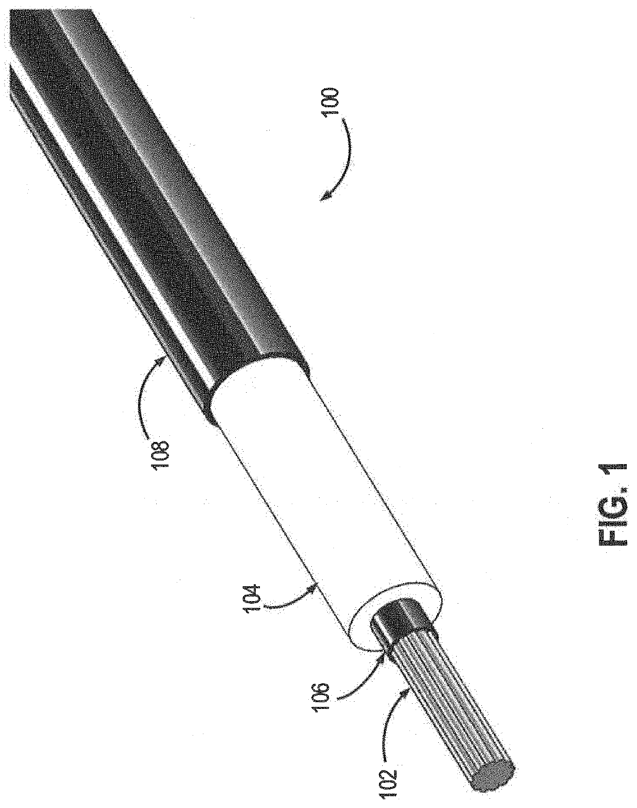
[0020]FIG. 1 illustrates a heater cable 100 with each layer subsequently stripped to clearly illustrate its construction in accordance with at least one embodiment of the invention. The heater cable 100 includes a conductor 102 at its core. The conductor 102 can be of any suitable conductive material including tinned copper, nickel plated copper, aluminum, steel, gold, platinum, silver, and others. The conductor 102 may be a solid conductor wire or may be stranded wire. The conductor 102 is encapsulated within a non-conducting electrical insulation layer 104. The electrical insulation layer 104 may be of any suitable material including silicone, perfluoroalkoxy (PFA) polymer, ethylene propylene diene monomer (EPDM) rubber, ethylene propylene rubber (EPR), cross-linked polyethylene (XPLE), and others. In some embodiments, the circumference of the conductor 102 is entirely in physical contact with the electrical insulation layer 104—that is, there are no layers or other components dis...


PUM

PropertyMeasurementUnit
voltageaaaaaaaaaa
voltageaaaaaaaaaa
voltageaaaaaaaaaa

Abstract

A skin effect heating system for long pipelines includes a heater cable disposed in a ferromagnetic or other conductive heat tube. A semiconductive jacket contacts the inner surface of the heat tube, where the charge density of the return current carried by the heat tube is at its highest. The semiconductive jacket material has a resistivity that is sufficiently low to reduce or eliminate arcing events such as corona discharge by allowing accumulated charge on the heat tube to dissipate. The resistivity is also high enough to prevent the return current from flowing into or through the semiconductive outer layer, so that heat production capacity of the system is maximized.

Description

CROSS-REFERENCE TO RELATED APPLICATIONS[0001]This application is a continuation-in-part and claims the benefit of U.S. patent application Ser. No. 15 / 591,949, entitled “Shielded Wire for High Voltage Skin Effect Trace Heating,” filed May 10, 2017, which is a nonprovisional application claiming the benefit of priority from U.S. Prov. Pat. App. Ser. No. 62 / 334,346, filed under the same title on May 10, 2016, both of which patent applications are incorporated fully herein by reference.BACKGROUND OF THE INVENTION[0002]In the oil and gas industry, pipelines must be heated over distances of many miles. Skin effect electric heat tracing systems are ideally suited for long transfer pipelines up to 12 miles (20 km) per circuit. The system is engineered for the specific application. Applications for this system include material transfer lines, snow melting and de-icing, tank foundation heating, subsea transfer lines and prefabricated, pre-insulated lines. In a skin-effect heating system, heat...

Claims


Application Information

Patent Timeline
Patent Type & Authority Patents(United States)
IPC IPC(8): H05B3/56C08L101/04F16L53/34H01B7/42H05B3/00H05B3/14C08L101/00F16L53/38
CPCH05B3/56C08L101/00C08L101/04F16L53/34H01B7/428H05B3/0004H05B3/145F16L53/38
Inventor DONG, WESLEYBECKER, PAULPARMAN, DAVID
Owner NVENT SERVICES GMBH
Why Eureka
Try Eureka