
Coil spring

a coil spring and coil spring technology, applied in the field of coil springs, can solve problems such as the possibility of reducing production efficiency, and achieve the effect of preventing reciprocal entanglement without increasing weight or cos

Active Publication Date: 2021-05-04
NHK SPRING CO LTD
View PDF21 Cites 1 Cited by
  • Summary
  • Abstract
  • Description
  • Claims
  • Application Information

AI Technical Summary

Benefits of technology

The present invention is related to a coil spring that can prevent mutual entanglement without adding weight or cost. The technical effect of this invention is to improve the performance and reliability of the coil spring without increasing its cost or weight.

Problems solved by technology

In this type of coil spring, when a plurality of coil springs are accommodated together at random, the coil springs become entangled with each other, and for example, there is a possibility of reduction in production efficiency.

Method used


Image

  • Coil spring
  • Coil spring
  • Coil spring

Examples


Embodiment Construction

[0020]As a result of intensive studies by the present inventors, the following findings were found.

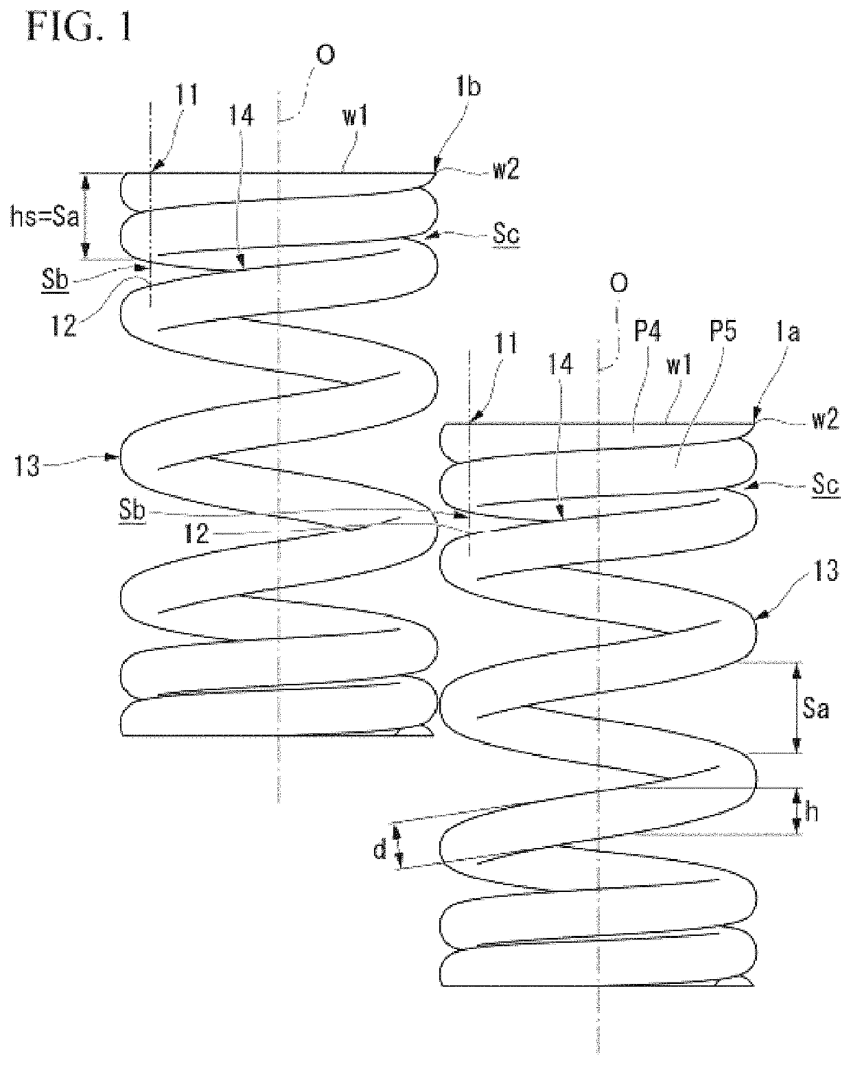
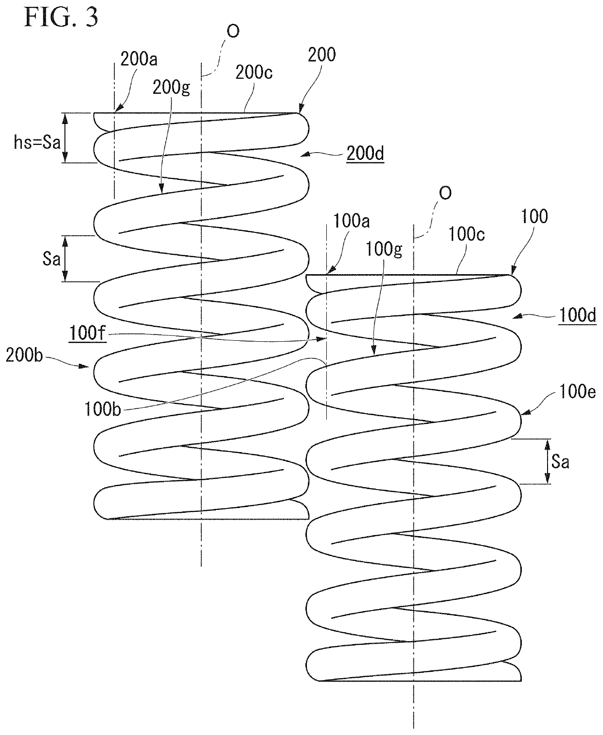
[0021]In conventional coil springs 100 and 200 shown in FIG. 3, corresponding portions 100a and 200a are provided at end portions in a direction of the coil axis O of the coil springs 100 and 200, and the corresponding portions 100a and 200a have a whole size hs of the plurality of wire materials adjacent to each other in the direction of the coil axis O equal to a maximum value Sa of a gap between the wire materials in the coil springs 100 and 200. In the shown example, the coil springs 100 and 200 are closed end springs in which pitches in active coil portions 100e and 200b are equal. Therefore, the maximum value Sa of the wire material gap is equal over substantially the entire region of the active coil portions 100e and 200b.

[0022]The corresponding portion 100a of one coil spring 100 enters the wire material gap of the other coil spring 200. Along with this, the wire material in t...


PUM


Abstract

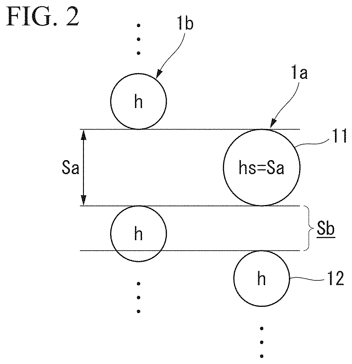
The present invention provides a coil spring, in which a corresponding portion is provided at an end portion in a direction of a coil axis, the corresponding portion having a whole size in the direction of the coil axis of the plurality of wire materials adjacent to each other in the direction of the coil axis equal to a maximum value of a gap in the direction of the coil axis between wire materials adjacent to each other in the direction of the coil axis of the coil spring, a gap in the direction of the coil axis between the corresponding portion and a wire material adjacent to the corresponding portion on an inner side in the direction of the coil axis is smaller than a wire height in an active coil portion of the coil spring, and at the end portion of the direction of the coil axis, a gap in the direction of the coil axis between a portion extending around the coil axis from the corresponding portion to a distal end portion side of the wire material and a wire material adjacent to the portion on the inner side in the direction of the coil axis gradually decreases from the corresponding portion toward the distal end portion side of the wire material around the coil axis.

Description

CROSS REFERENCE TO RELATED APPLICATIONS[0001]This is the U.S. national stage of application for International Application No. PCT / JP2017 / 013172, filed on Mar. 30, 2017. Priority under 35 U.S.C. § 119(a) and 35 U.S.C. § 365(b) is claimed from Japanese Application No. 2016-073519, filed on Mar. 31, 2016, the disclosures all of which are also incorporated herein by reference.TECHNICAL FIELD[0002]The present invention relates to a coil spring.[0003]Priority is claimed on Japanese Patent Application No. 2016-073519, filed Mar. 31, 2016, the content of which is incorporated herein by reference.BACKGROUND ART[0004]In related art, a coil spring formed by winding a wire member around a coil axis has been widely used.[0005]In this type of coil spring, when a plurality of coil springs are accommodated together at random, the coil springs become entangled with each other, and for example, there is a possibility of reduction in production efficiency.[0006]In the coil spring shown in the followin...

Claims


Application Information

Patent Timeline
Patent Type & Authority Patents(United States)
IPC IPC(8): F16F1/04F16F1/06
CPCF16F1/047F16F1/06F16F2234/02F16F2238/026
Inventor WATANABE, TOSHINORIITO, HIDEMASATAKAMURA, NORITOSHIYAMAMOTO, FUMIOTAKAHASHI, FUMIO
Owner NHK SPRING CO LTD
Learn More