
Pneumatic fender

a pneumatic and fender technology, applied in the field of pneumatic fender, can solve the problems of unstable shape of fender, inability to reinforce the hemispherical portion, etc., and achieve the effect of expanding the overall shape and greatly in diameter

Active Publication Date: 2021-04-06
THE YOKOHAMA RUBBER CO LTD
View PDF5 Cites 0 Cited by
  • Summary
  • Abstract
  • Description
  • Claims
  • Application Information

AI Technical Summary

Benefits of technology

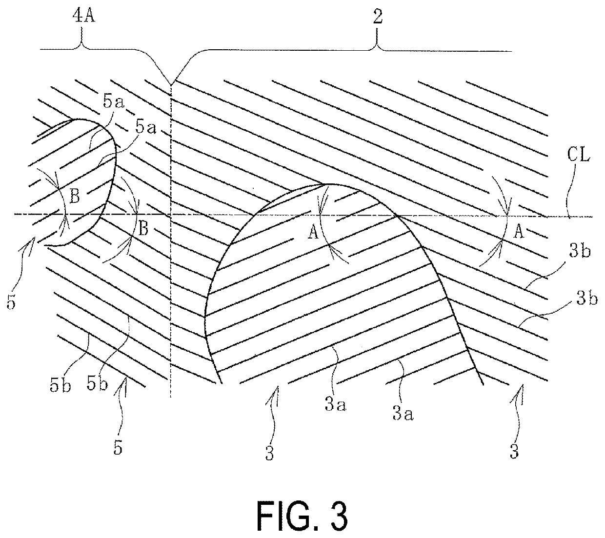
[0008]According to an embodiment of the present invention, not only in the reinforcing layers constituting the body portion, but also in a predetermined range in the reinforcing layers constituting each of the hemispherical portions near the boundary with the body portion, cords of the reinforcing layers layered adjacent to each other meet each other, and in a neutral state without expansion, a cord angle is set from 15° to 45° with respect to the longitudinal direction of the fender. Accordingly, when the fender is filled with air to be set to a specified internal pressure, the cord angle tends to increase to a stable static angle, and thus, the body portion and the predetermined range of the hemispherical portion consecutive to the body portion can be enlarged greatly in diameter and expanded. Thus, the fender can be expanded more greatly during use than when the fender is not in use, such as when stored, transported, or the like, and can correct distortion at or near a boundary between the body portion and each of the hemispherical portions at both ends. In addition, the overall shape of the fender can be expanded more similarly than in the related art.

Problems solved by technology

However, unlike the reinforcing layer of the body portion, a reinforcing layer of a hemispherical portion does not have specifications in which a cord angle is set to from 15° to 45° in the neutral state.
Accordingly, when the interior of the fender is expanded to a specified internal pressure, distortion occurs at or near a boundary between the body portion and each of the hemispherical portions at both ends, and the fender tends to have an unstable shape.

Method used


Image

  • Pneumatic fender
  • Pneumatic fender
  • Pneumatic fender

Examples


Embodiment Construction

[0015]A pneumatic fender according to embodiments of the present invention will be described below with reference to embodiments illustrated in the figures.

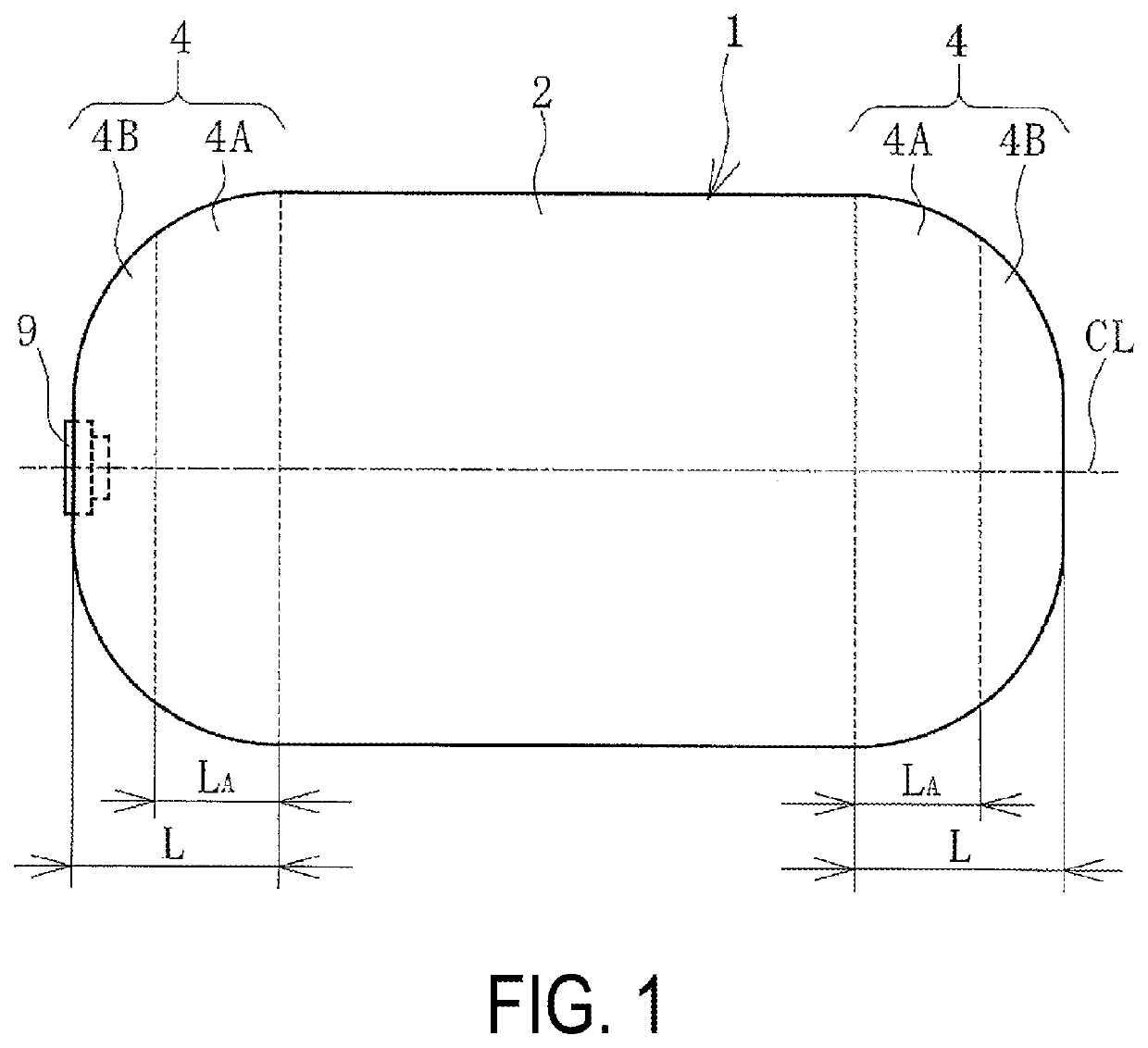
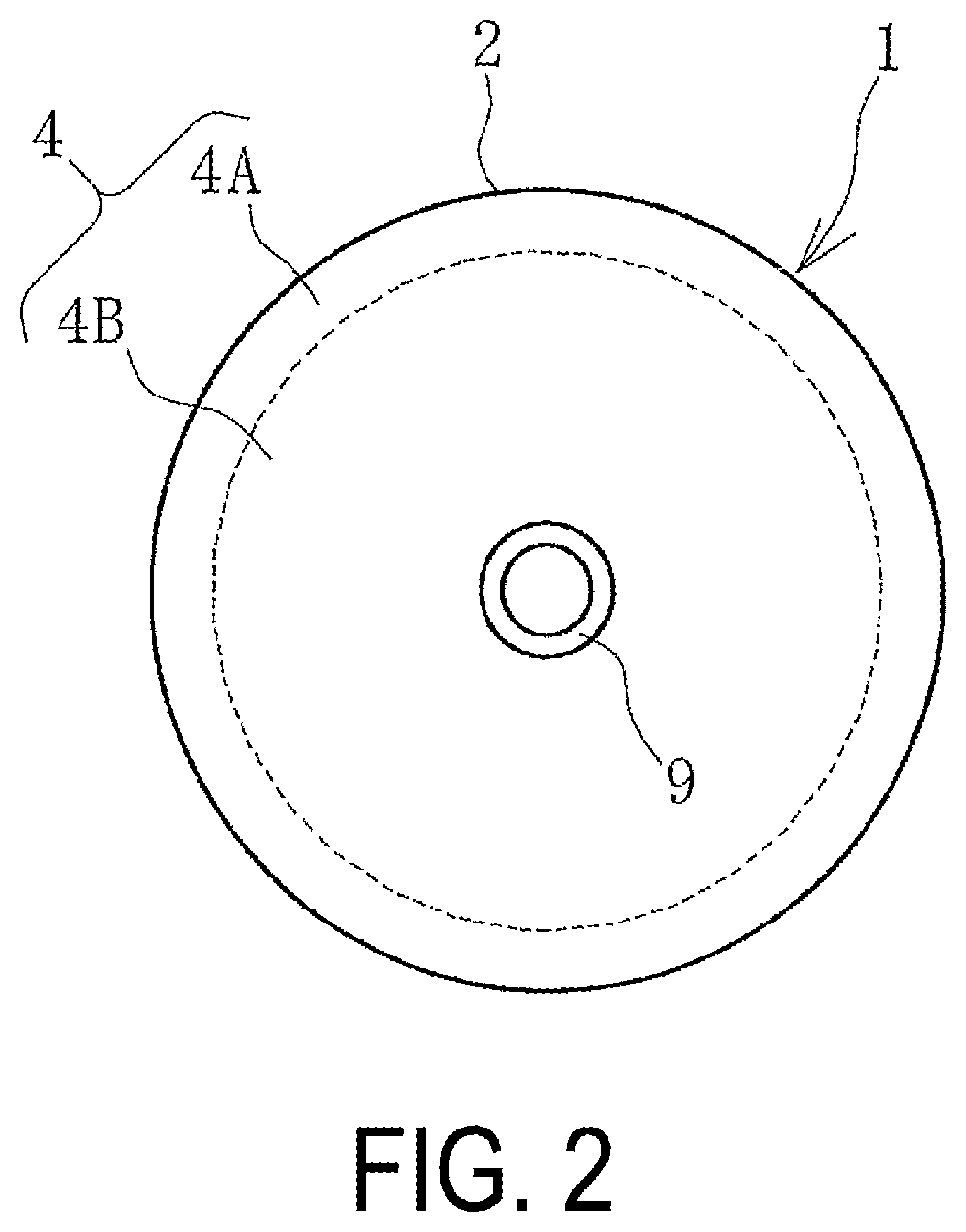
[0016]As illustrated in FIGS. 1 to 5, a pneumatic fender 1 according to an embodiment of the present invention (hereinafter referred to as a fender 1) includes hemispherical portions 4 each having a bowl shape at both ends of a body portion 2 having a cylindrical shape. In this embodiment, a mouthpiece portion 9 is provided in one of the hemispherical portions 4, but may be provided in both of the hemispherical portions 4. One dot chain line CL in the figure is a center line of the fender 1 passing through the circular center of each of the hemispherical portions 4.

[0017]The body portion 2 is configured by layering a plurality of reinforcing layers 3 between an inner layer rubber 6 and an outer layer rubber 7. Each of the hemispherical portions 4 is also configured by layering a plurality of reinforcing layers 5 between the inner...


PUM


Abstract

In a pneumatic fender, reinforcing layers of a body portion and reinforcing layers of a predetermined range in the longitudinal direction of a fender near a boundary between each hemispherical portion and the body portion are formed by aligning cords of reinforcing layers of the body portion and that of the predetermined range in parallel, and in a neutral state without expansion, the cords of the reinforcing layers of the body portion meet each other and the cords of the reinforcing layers of the predetermined range meet each other, and cord angles A and B are each set to from 15° to 45° with respect to the longitudinal direction of the fender. When the interior of the fender is set to a specified internal pressure, the cord angles A and B increase to extent of a static angle, and the body portion and the predetermined range expand.

Description

TECHNICAL FIELD[0001]The present invention relates to a pneumatic fender, and particularly relates to a pneumatic fender that can expand more greatly during use than when the pneumatic fender is not in use, such as when stored, transported, or the like, and that can correct distortion at or near a boundary between the body portion and each of the hemispherical portions at both ends to expand an overall shape more similarly than in the related art.BACKGROUND ART[0002]A pneumatic fender generally includes hemispherical portions each having a bowl shape at both ends of a body portion having a cylindrical shape, and the body portion is configured by layering a plurality of reinforcing layers between an inner layer rubber and an outer layer rubber. Each of the plurality of reinforcing layers is a cord layer formed by aligning a number of cords in parallel, and the cords are disposed at a predetermined cord angle with respect to the longitudinal direction of the fender (cylinder axial dir...

Claims


Application Information

Patent Timeline
Patent Type & Authority Patents(United States)
IPC IPC(8): E02B3/26
CPCE02B3/26Y02A30/30B63B2059/025
Inventor TSUCHIYA, KOUKOSHIBUYA, MINAMIHASEGAWA, KEIICHIHOU, GANGSHIBAYAMA, SATOSHIIEMOTO, AKIHIROONO, SHUNICHIKANEKO, MICHITO
Owner THE YOKOHAMA RUBBER CO LTD
Learn More