
Magnetic phonograph record stabilizer

a magnetic stabilizer and phonograph record technology, applied in the field of phonograph records, can solve the problems of record vibrating, affecting the rotation speed of the turntable, and the tendency of the planar phonograph record itself to vibrate vertically,

Active Publication Date: 2021-02-23
TIPPETTS GLEN
View PDF10 Cites 1 Cited by
  • Summary
  • Abstract
  • Description
  • Claims
  • Application Information

AI Technical Summary

Benefits of technology

The invention offers a solution for better sound reproduction from plastic or metal phonograph records that are played on conventional turntables. These turntables usually have a needle that moves along the grooved surface of the record to pick up the sound track. To protect the surface of the record, the turntable has a flexible pad that rests on top of the record while it plays. This invention improves the quality of the sound from plastic or metal records.

Problems solved by technology

However, a phonograph recording is analog, and it is said that such allows for reproduction of subtle analog sound waves which are lost during digital compilation to bits and data.
However, the matching of the rotation of the phonograph record to the rotation speed of the turntable, can be affected by slippage if the turntable surface is too slick or if the turntable is bumped.
An additional problem with conventional turntables is the tendency for the planar phonograph record itself to vibrate vertically or in a translating direction along the axis of the spiral.
Such can be caused by the sound waves emanating from the loudspeakers reproducing the sound recorded on the record, which is known to cause the record to vibrate.
Such vibration of the material forming the phonograph record frequently can cause the needle, following the recording track in the spiral groove, to bounce or to rise higher within the grove thereby reducing the quality of the sound.
Various other limitations of the related art are known or will become apparent to those skilled in the art upon a reading and understanding of the specification below and the accompanying drawings.

Method used


Image

  • Magnetic phonograph record stabilizer
  • Magnetic phonograph record stabilizer
  • Magnetic phonograph record stabilizer

Examples


Embodiment Construction

[0040]In this description, the directional prepositions of up, upwardly, down, downwardly, front, back, top, upper, bottom, lower, left, right and other such terms refer to the device as it is oriented and appears in the drawings and are used for convenience only and such are not intended to be limiting or to imply that the device has to be used or positioned in any particular orientation.

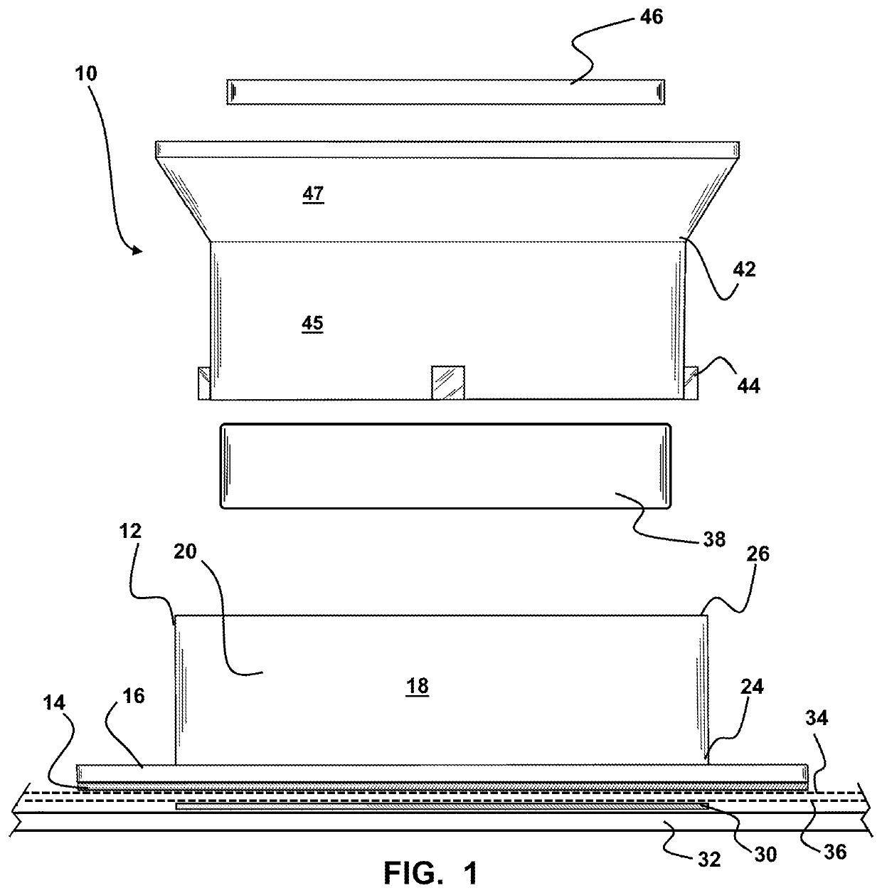
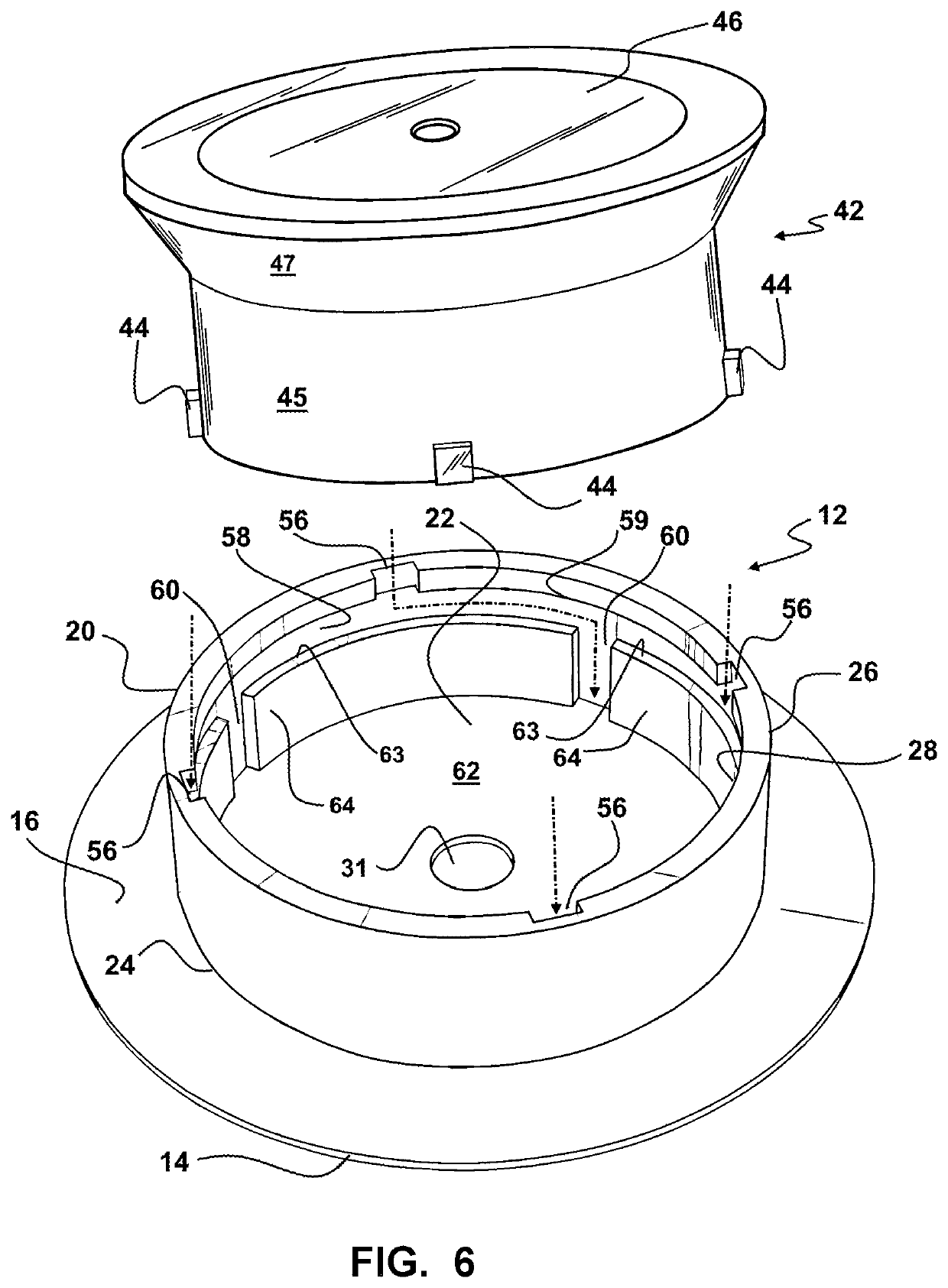
[0041]Now referring to drawings in FIGS. 1-8, wherein similar components are identified by like reference numerals, there is seen in FIG. 1, an exploded view of the components of the device 10 herein. As shown, a base 12 may include a pad 14 formed of flexible and compressible material, such as one formed of cork or rubber, on a lower surface thereof, and upon a lower surface of an annular shoulder 16 extending circumferentially from and around the exterior surface 18 of a base sidewall 20 of the base 12. This base sidewall 20 surrounds and defines a cavity 22 (FIG. 6) of the base 12 extending from...


PUM


Abstract

A magnetic phonograph record stabilizer is configured to hold a phonograph record in a biased contact against a turntable. The stabilizer features a base which is engaged with a magnetic housing which is moveable from a first position where magnetic attraction biases the base toward the turntable. The magnetic housing is slidable to a second position eliminating the biasing from the magnetic flux so the stabilizer can be removed from the turntable.

Description

FIELD OF THE INVENTION[0001]The disclosed device concerns phonograph records played upon rotating turntables. More particularly, it relates to a magnetic stabilizer providing releasable magnetic pressure to hold a phonograph record fixedly positioned while rotating on a phonograph turntable to enhance sound produced therefrom.BACKGROUND OF THE INVENTION[0002]The phonograph record is an analog sound storage component formed as a planar disc with recorded sound inscribed on a surface in the form of a modulated spiral groove. The groove providing the analog sound conventionally starts near the periphery of the round planar disc and ends near the center of the disc.[0003]In use, the planar disk is situated to a removable engagement positioned atop a rotating turntable. An aperture, communicating through the center of the round planar disk forming each phonograph record, is sized to engage over and around a spindle situated in the center of the rotating turntable. The locating of the pla...

Claims


Application Information

Patent Timeline
IPC IPC(8): G11B3/61F16C39/06
CPCG11B3/61F16C39/066F16C2370/12
Inventor TIPPETTS, GLEN
Owner TIPPETTS GLEN
Learn More