Power transmission shaft
a technology of transmission shaft and circlip, which is applied in the direction of yielding coupling, coupling, fastening means, etc., can solve the problems that the visual recognition of the engagement stop state of the circlip (retaining ring) cannot be externally recognized, and the appropriate attachment of the propeller shaft (the power transmission shaft) cannot be carried out. , to achieve the effect of preventing the drop-out of the circlip, improving the workability of the linkage, and preventing the drop-ou
- Summary
- Abstract
- Description
- Claims
- Application Information
AI Technical Summary
Benefits of technology
Problems solved by technology
Method used
Image
Examples
first embodiment
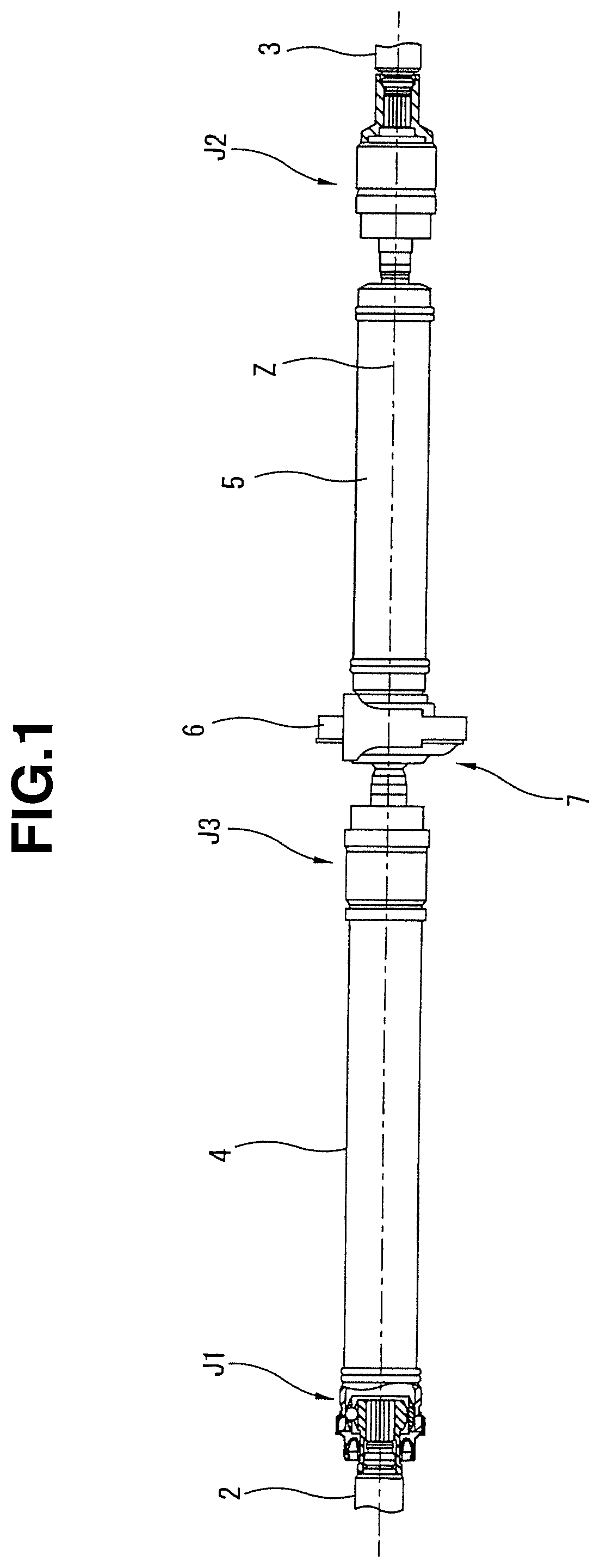
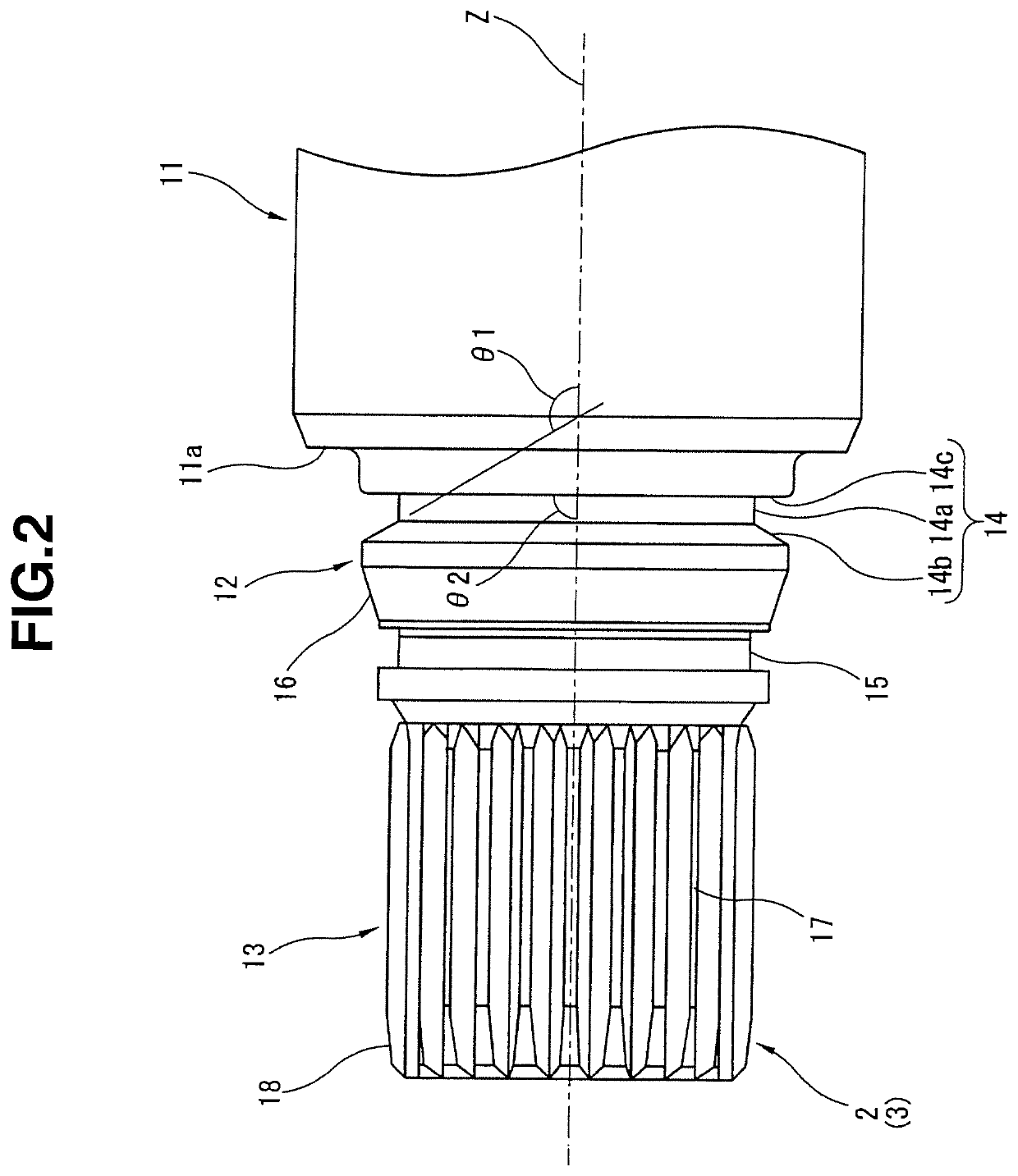
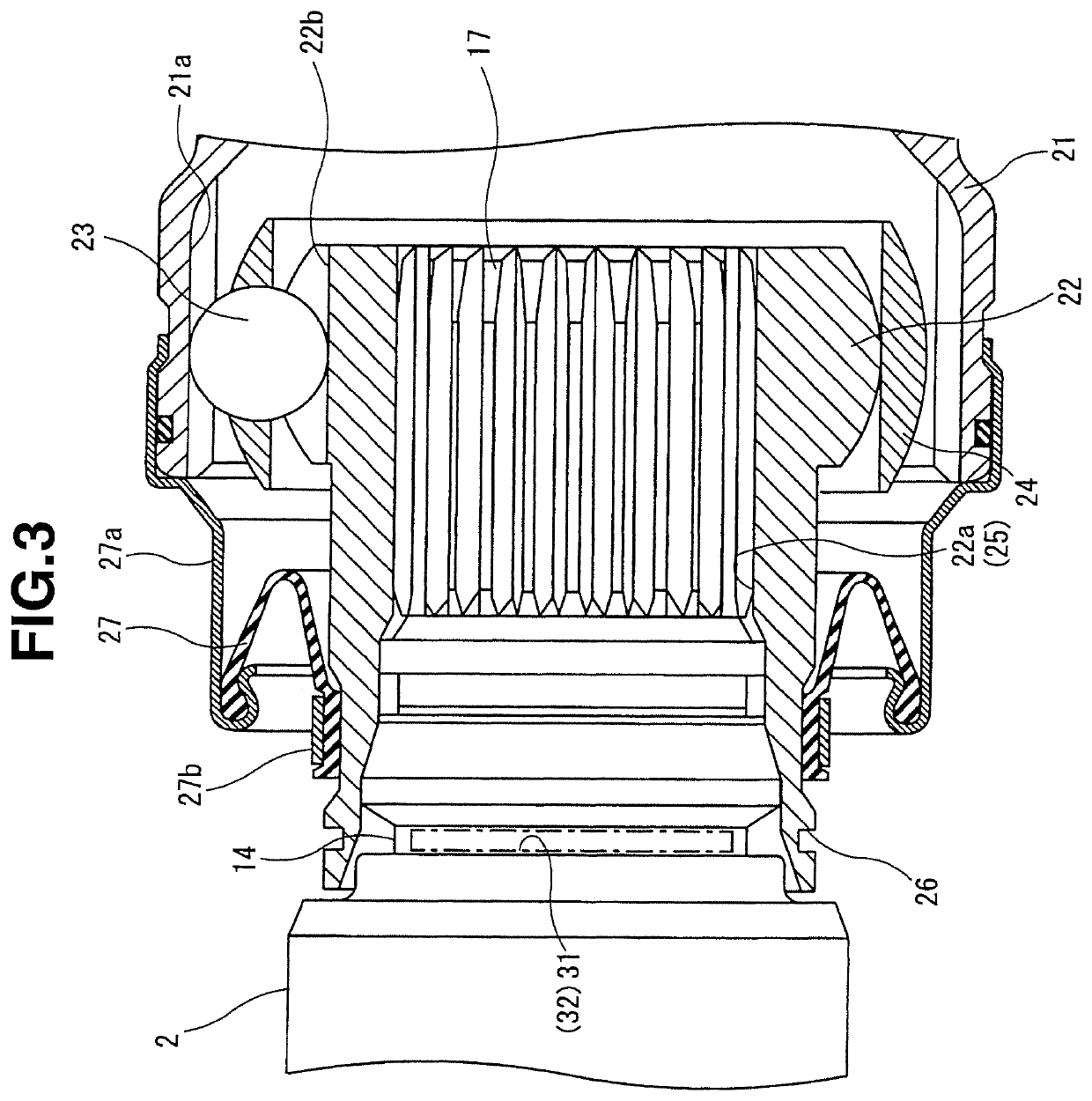
[0028]FIGS. 1 through 13(b) show a first preferred embodiment of the power transmission shaft (also called the propeller shaft) according to the present invention. FIG. 1 shows a side view of the power transmission shaft (propeller shaft) representing a whole of the propeller shaft (power transmission shaft).
[0029]It should be noted that, in the following description, for convenient purposes, a left side of FIG. 1 is explained as a front, a right side of FIG. 1 is explained as a rear, a direction along a rotation center axial line in FIG. 1 is explained as an axial (shaft) line, and a direction around a rotational center axial (shaft) line is explained as a peripheral direction.
[0030](Structure of power transmission shaft) Power transmission shaft 1 includes: a driving shaft 4 integrally rotatably linked to an input shaft 2 interlinked to a transmission (not shown) via a first constant velocity (universal) joint J1; and a driven shaft 5 integrally rotatably linked to an output shaft...
second embodiment
[0094]FIG. 15 shows a second preferred embodiment of the propeller shaft (power transmission shaft) according to the present invention. In the second embodiment, the shape of circlip (retaining ring) 8 in the case of the first embodiment is modified. It should be noted that the basic structure of the second embodiment is the same as the first embodiment except the modification of circlip (retaining ring) 8. Hence, for the same structure as the first embodiment, the same reference numerals are provided and their explanations will be omitted (the same as those described below).
[0095]That is to say, circlip (retaining ring) 81 in this embodiment is structured in such a way that first and second projection sections 41a, 42a are formed as projection sections in which portions of respective insertion sections 41, 42 are projected in the outsides of the radial directions on first and second insertion sections 41, 42 which are formed linearly in the first embodiment.
[0096]In other words, ci...
third embodiment
[0098]FIG. 16 shows a third preferred embodiment of the propeller shaft (power transmission shaft) according to the present invention.
[0099]In this embodiment, the shape of circlip (retaining ring) 8 described in the first embodiment is modified.
[0100]Circlip (retaining ring) 82 in this embodiment includes a projection section 43a formed in such a way that a portion of connection section 43 is offset toward a more radially outer side of cylindrical section 30 than an outer peripheral surface 30c of cylindrical section 30. In addition, a predetermined gap C2 is formed radially between projection section 43a and cylindrical section 30 in an appropriate mounting state of circlip (retaining ring) 82.
[0101]In addition, in circlip (retaining ring) 82 in this embodiment, first and second engagement sections 44, 45 are bent in folded shapes toward the outside (radially outside). At the same time, portions of bending sections which are brought in contact with cylindrical section 30 (retainin...
PUM
 Abstract
Description
Claims
Application Information
 - R&D
- Intellectual Property
- Life Sciences
- Materials
- Tech Scout
- Unparalleled Data Quality
- Higher Quality Content
- 60% Fewer Hallucinations
Browse by: Latest US Patents, China's latest patents, Technical Efficacy Thesaurus, Application Domain, Technology Topic, Popular Technical Reports.
© 2025 PatSnap. All rights reserved.Legal|Privacy policy|Modern Slavery Act Transparency Statement|Sitemap|About US| Contact US: help@patsnap.com


