Set of interchangeable crimp units
a technology of crimp unit and crimp head, which is applied in the field of interchangeable crimp unit, can solve problems such as outage tim
- Summary
- Abstract
- Description
- Claims
- Application Information
AI Technical Summary
Benefits of technology
Problems solved by technology
Method used
Image
Examples
Embodiment Construction
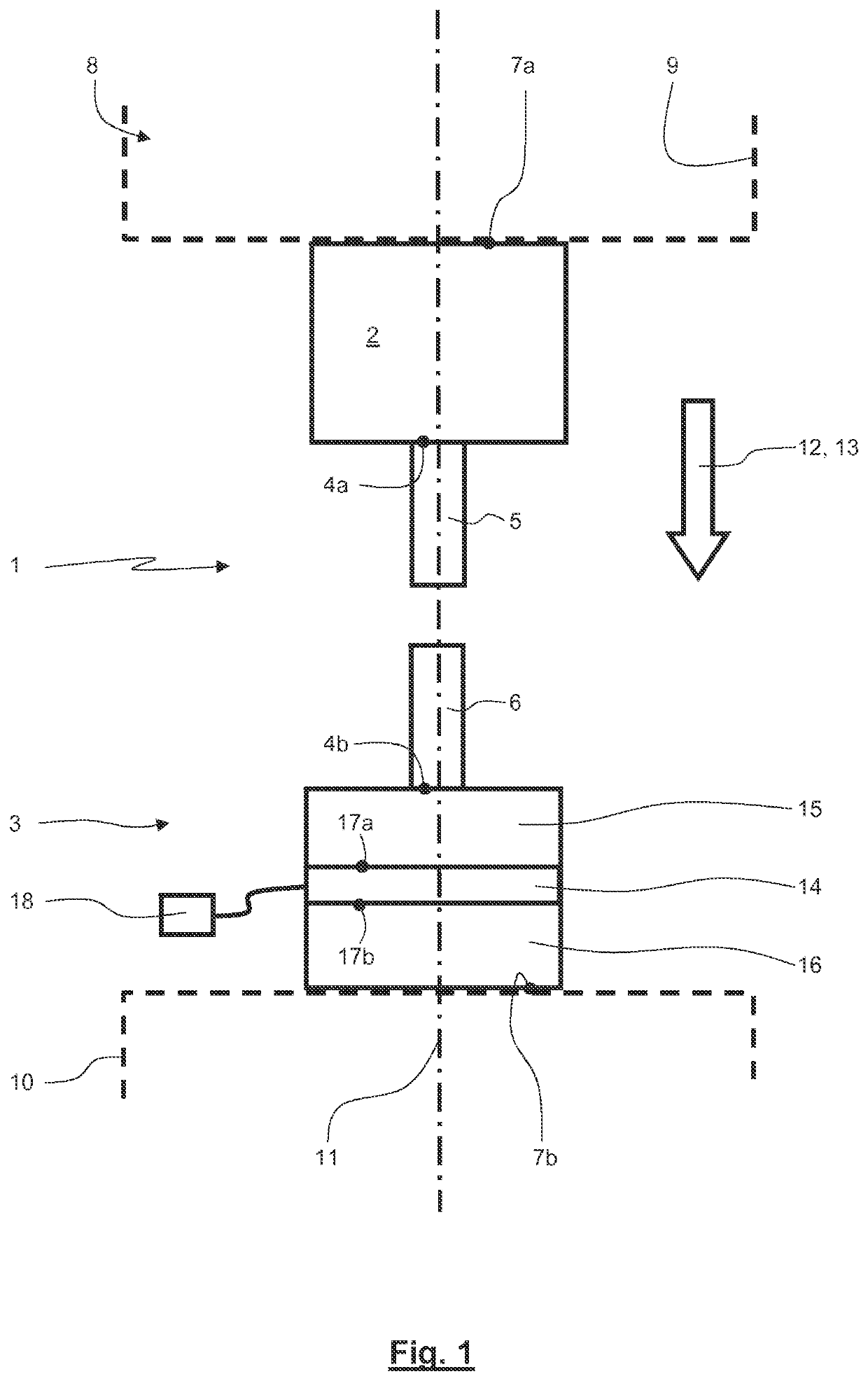
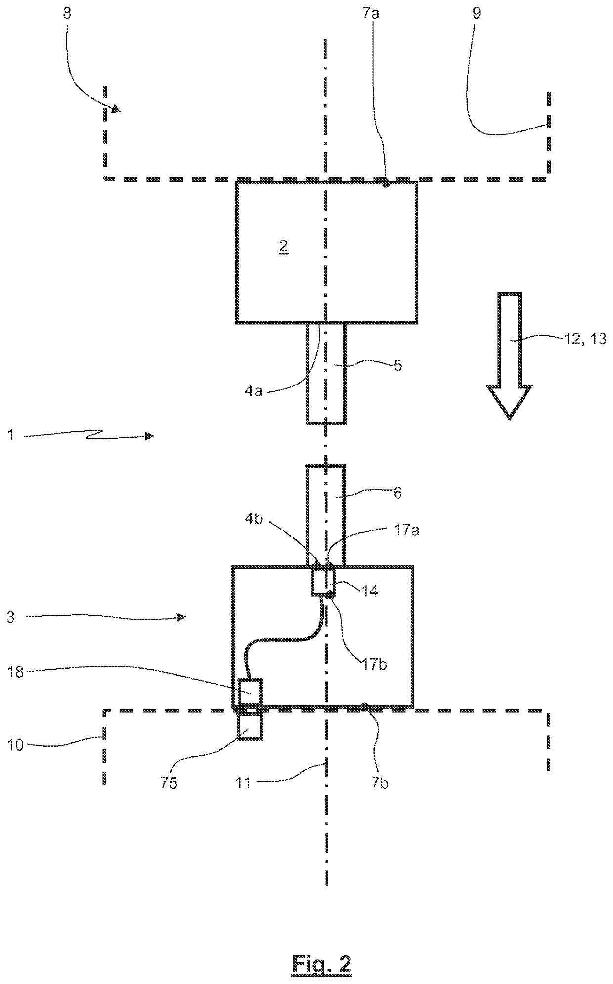
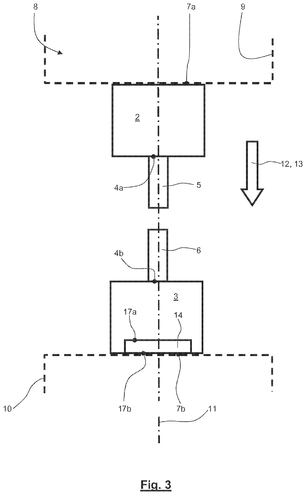
[0061]FIG. 1 is a rough schematic view of a crimp unit 1. The crimp unit 1 is built with die holders 2, 3 wherein one die holder 2 builds a kind of moved punch and the other die holder 3 builds a kind of fixed anvil. At the opposing faces the die holders 2, 3 each build receivers 4a, 4b designated for holding dies or die halves 5, 6 at the die holders 2, 3. Furthermore, the die holders 2, 3 comprise coupling regions located at the back faces or at the surfaces facing away from each other. The coupling regions 7a, 7b serve for coupling the die holders 2, 3 with a crimping machine 8. In the shown embodiment, only an upper part 9 and a lower part 10 (shown in dashed line) of the crimping machine 8 are shown. During the crimping process the upper part 9 is moved by any actuator (in particular a hydraulic or electric actuator) along a crimping path 12 along a crimping axis 11 towards the lower part 10. The actuator produces a crimping force 13. Along the crimping path 12 and by means of ...
PUM
| Property | Measurement | Unit |
|---|---|---|
| crimping force | aaaaa | aaaaa |
| transparent | aaaaa | aaaaa |
| lengths | aaaaa | aaaaa |
Abstract
Description
Claims
Application Information
 - R&D
- Intellectual Property
- Life Sciences
- Materials
- Tech Scout
- Unparalleled Data Quality
- Higher Quality Content
- 60% Fewer Hallucinations
Browse by: Latest US Patents, China's latest patents, Technical Efficacy Thesaurus, Application Domain, Technology Topic, Popular Technical Reports.
© 2025 PatSnap. All rights reserved.Legal|Privacy policy|Modern Slavery Act Transparency Statement|Sitemap|About US| Contact US: help@patsnap.com


