
Lubrication device having a plurality of lubrication liquid recovery tanks, and optimized and reliable delivery means to a main tank

a technology of lubrication device and liquid recovery tank, which is applied in the direction of gear lubrication/cooling, rotocraft, gearbox, etc., can solve the problems of significant space and mass, complex and difficult operation of the lubrication device of this mechanical system, and achieve the effect of efficient operation throughout the flight of the aircra

Active Publication Date: 2020-11-24
EUROCOPTER
View PDF28 Cites 6 Cited by
  • Summary
  • Abstract
  • Description
  • Claims
  • Application Information

AI Technical Summary

Benefits of technology

[0031]The present invention is intended to simplify the delivery system of the lubrication liquid between one or more recovery tanks and a main tank, while minimizing the mass thereof and limiting the risk of malfunction.
[0069]Furthermore, the lubrication device may include a main lubrication circuit and one or more backup lubrication circuits so that the mechanical system is lubricated continuously, regardless of any malfunction of any lubrication circuit, and therefore works efficiently throughout the flight of the aircraft.

Problems solved by technology

Without such lubrication, operation of the mechanical system may be quickly degraded or even become impossible.
This pressure drop may be the result of a failure of the flow generator or a leak in the main lubrication circuit or the cooling circuit.
Furthermore, a mechanical system may have several zones that require significant lubrication.
The use of such a single casing can sometimes cause significant space and mass problems, which may have adverse effects, notably for a mechanical system in an aircraft.
Separating this casing into several casings, each forming a recovery tank for the lubrication liquid coming from these different zones, also causes problems of complexity and operation of the lubrication device of this mechanical system.
This increase in the number of pumps has a number of drawbacks, notably an increase in the mass and in the cost of the lubrication device, as well as an increase in the risk of faults in the lubrication device, thereby tending to reduce the reliability thereof.
This gravity-based delivery therefore requires the main tank to be arranged at least partially below the recovery tanks, which may have an impact on installation of the recovery tanks and of the main tanks, and consequently increase the size of the lubrication device.
As before, the use of these supplementary recovery pumps results in an increase in mass, in cost and in the risk of failure of the lubrication device.
Furthermore, this delivery system becomes more complex if the inclination of the mechanical system varies during operation.
Indeed, following these variations in inclination of the recovery tanks and of the main tank, the main tank may no longer be positioned beneath the recovery tanks.
Consequently, delivery of the lubrication liquid between the recovery tanks and the main tank under the effect of gravity may be interrupted, resulting in disturbances or even stoppage of lubrication of the mechanical system.
Furthermore, these variations in the inclination of the recovery tanks and of the main tank result in a change of the position of the volume of lubrication liquid in each tank, which may result in a stoppage of the supply of lubrication liquid to the ducts, and consequently the stoppage of the supply to the main tank.
Equally, this change in the position of the volume of lubrication liquid in each tank may cause a stoppage of the supply to the main tank by the supplementary recovery pumps, the suction point of each pump being then outside the volume of lubrication liquid.
Furthermore, each pump may also be damaged by cavitation.
Furthermore, lubrication liquid retention zones may appear in the recovery tanks, preventing the lubrication liquid from being delivered to the main tank and consequently from being used by the lubrication device.
Furthermore, filing-sized particles can get trapped and accumulate in these retention zones.
In these two cases, the delivery device uses mechanical drive means that are at risk of failure and that add significant mass to the aircraft.
Furthermore, the complexity of a lubrication device designed to lubricate several zones of a mechanical system that is subject to variations in inclination can be further accentuated if these lubrication devices have a main lubrication circuit and at least one backup lubrication circuit.

Method used


Image

  • Lubrication device having a plurality of lubrication liquid recovery tanks, and optimized and reliable delivery means to a main tank
  • Lubrication device having a plurality of lubrication liquid recovery tanks, and optimized and reliable delivery means to a main tank
  • Lubrication device having a plurality of lubrication liquid recovery tanks, and optimized and reliable delivery means to a main tank

Examples


Embodiment Construction

[0071]Elements shown in several different figures are indicated using the same reference signs.

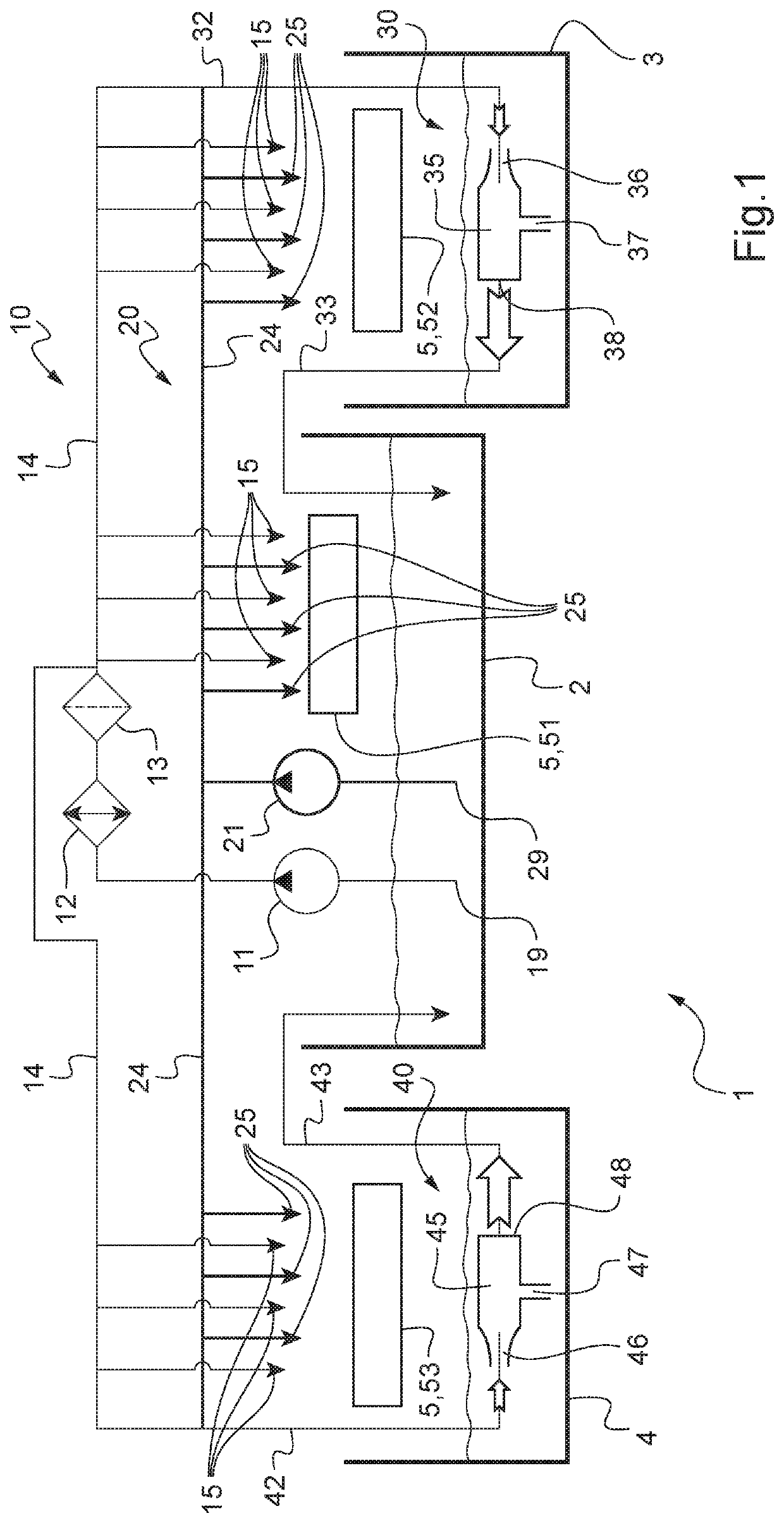
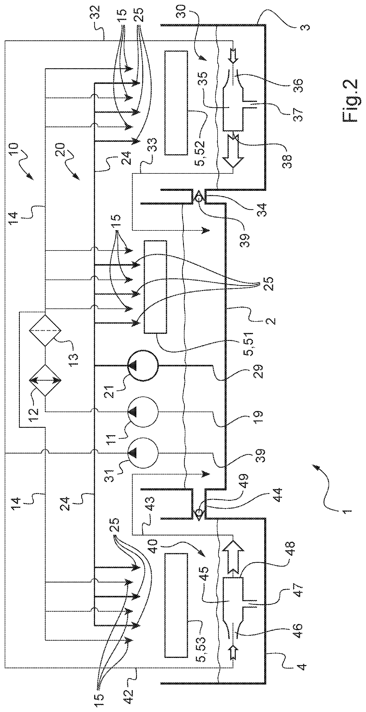
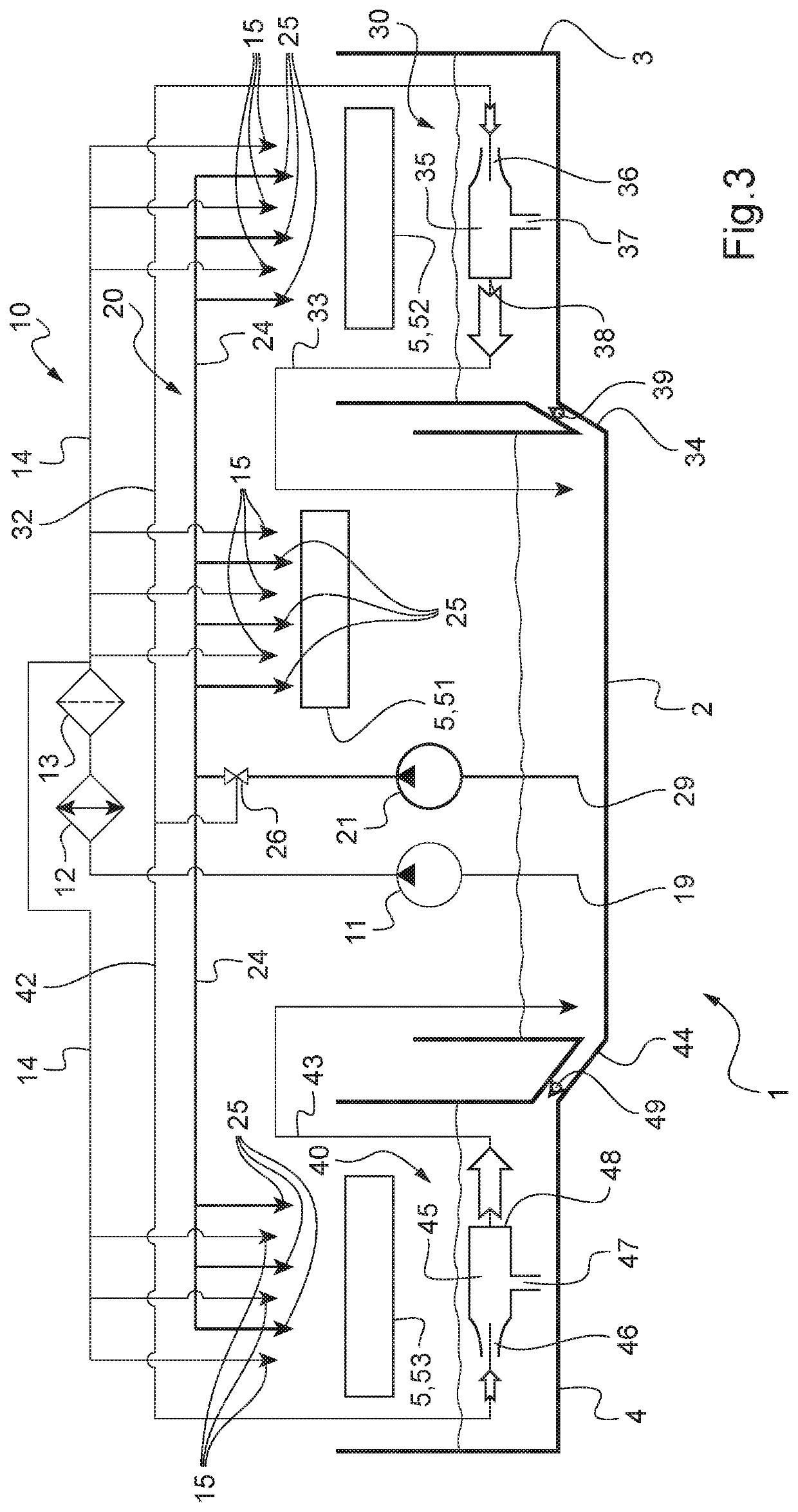
[0072]Each lubrication device 1 shown in FIGS. 1 to 4 is intended to lubricate a mechanical system 5 having rotary elements, such as shafts and bearings, and elements for transmitting power and reducing or increasing rotational speed, such as pinions and / or gears. This mechanical system 5 is for example a main power gear box that is fitted to a rotary-wing aircraft and that has three zones 51, 52, 53 that require significant lubrication, as shown in FIGS. 1 to 3.

[0073]In order to efficiently lubricate these three zones 51, 52, 53 of the mechanical system 5, the lubrication device 1 includes, in all of the examples shown in FIGS. 1 to 3, a main tank 2 containing a lubrication liquid, two recovery tanks 3, 4, a main lubrication circuit 10, a backup lubrication circuit 20, two flow generators 11, 21 and two delivery systems 30, 40 attached respectively to a recovery tank 3, 4.

[0074]The main l...


PUM


Abstract

A lubrication device of a mechanical system, the lubrication device having a main tank, at least one recovery tank, a lubrication circuit, a flow generator supplying the lubrication circuit with a lubrication liquid located in the main tank and a delivery system for each recovery tank. Each delivery system has an ejector arranged in a recovery tank and first and second conduits linking the ejector firstly to the lubrication circuit and secondly to the main tank in order to deliver the lubrication liquid located in the recovery tank to the main tank using the ejector.

Description

BACKGROUND OF THE INVENTION(1) Field of the Invention[0001]The present invention relates to the field of lubrication of power transmission systems, in particular power transmission systems designed for rotary-wing aircraft.2) Description of Related Art[0002]The present invention relates to a lubrication device having a plurality of lubrication liquid recovery tanks, as well as optimized and reliable delivery means to a main tank. This lubrication device is designed to lubricate a mechanical system and is particularly suited to lubrication of a power transmission system of a rotary-wing aircraft, hereinafter referred to as “transmission system”.[0003]Mechanical systems usually have rotary elements, such as shafts and bearings, and elements for transmitting power and reducing or increasing rotational speed, such as pinions and / or gears. To work correctly, mechanical systems require these elements to be lubricated and cooled, for example using a pressurized lubrication liquid such as o...

Claims


Application Information

Patent Timeline
Patent Type & Authority Patents(United States)
IPC IPC(8): F16H57/04B64C27/12F16H57/02
CPCB64C27/12F16H57/045F16H57/0442F16H57/0435F16H57/0436F16H2057/02043B64D35/00F16H57/0413
Inventor DE MEERSCHMAN, OLIVIER
Owner EUROCOPTER
Learn More