Power limiter configuration for audio signals

a technology of power limiter and audio signal, which is applied in the direction of volume compression/expansion having semiconductor devices, volume compression/expansion in untuned/low-frequency amplifiers, instruments, etc., can solve the problems of complex relationship between amplitude and output power, incur latency, and computationally expensive problems

Active Publication Date: 2020-11-03
BIAMP SYST LLC
View PDF2 Cites 8 Cited by
  • Summary
  • Abstract
  • Description
  • Claims
  • Application Information

AI Technical Summary

Problems solved by technology

One reason for a feedback compressor, rather than a feedforward compressor, is that the relationship between amplitude and output power is complex.
An attempt to predict output power by modelling the load could be performed, but that would be computationally expensive and incur latency.

Method used


Image

  • Power limiter configuration for audio signals
  • Power limiter configuration for audio signals
  • Power limiter configuration for audio signals

Examples


Embodiment Construction

[0029]Example embodiments include circuit configurations illustrated as logical systems and modules which perform certain tasks and operations to process data, such as an audio input signal and provide a modified output signal. Such configurations may support additional and / or fast attenuation sources, and enabled and disabled compression for a stored energy approach.

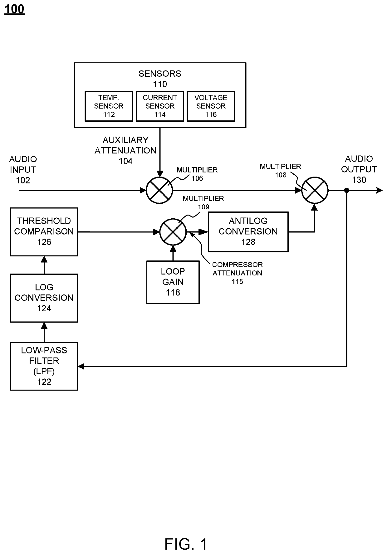
[0030]A load impedance will vary with frequency, and thus the power dissipation based on voltage will also vary with frequency. A feedback compressor permits measuring a true output power from voltage and current measurements without requiring information about the load.

[0031]FIG. 1 illustrates a block diagram of a feedback compressor circuit for burst power waveforms according to example embodiments. Referring to FIG. 1, the configuration or ‘circuit’100 may include an audio input 102, such as audio data from an audio source, which is multiplied by an external data source, such as sensors 110 which measure attenuation ...


PUM


Abstract

Example embodiments provide a process that includes one or more of receiving an audio signal at a feedback compressor circuit, determining how much to attenuate the audio signal when a power level of the audio signal exceeds a threshold power level, combining the audio signal with an auxiliary attenuation signal from an auxiliary attenuation source and a compressed attenuation signal from the feedback compressor circuit to create a combination signal, and generating an audio output signal of the feedback compressor circuit based on the combination signal.

Description

BACKGROUND OF THE INVENTION[0001]A power limiter circuit configuration may utilize a feedback compressor architecture. Within such a configuration, an output amplitude is monitored and compared against a threshold in the log domain. When the output amplitude exceeds the threshold, the difference, in decibels, is measured and multiplied by a constant loop gain to determine an attenuation amount. That attenuation is converted to a linear scale factor, is low-pass filtered, and applied to the input signal. The time constant of the low-pass filter determines how quickly signal compression is applied and released.[0002]One reason for a feedback compressor, rather than a feedforward compressor, is that the relationship between amplitude and output power is complex. The load impedance will vary with frequency, so the power dissipation, based on voltage, will vary with frequency as well. An attempt to predict output power by modelling the load could be performed, but that would be computati...

Claims


Application Information

Patent Timeline
Patent Type & Authority Patents(United States)
IPC IPC(8): H04R3/00H03G3/30H03G11/00G10L25/21H04R3/04H04R3/02H03F1/32
CPCH04R3/02G10L25/21H03G3/3005H04R3/04H03G11/008H03F1/3264H04R3/007H03G2201/106H04R2430/01H03F3/181H03F2200/03H03G7/002H03G7/007H03G7/08H03G2201/708
Inventor FAULSTICH, AARON
Owner BIAMP SYST LLC
Why Eureka
Try Eureka