Walking measurement device, walking measurement method, and program
a measurement device and walking technology, applied in the field of walking measurement devices, can solve the problems of compromising the accuracy of the step count, the pedometer is typically incapable of obtaining such information,
- Summary
- Abstract
- Description
- Claims
- Application Information
AI Technical Summary
Benefits of technology
Problems solved by technology
Method used
Image

Examples
first embodiment
[0021]In the following; a walking measurement device according to a first embodiment of the present invention will be described with reference to the accompanying drawings.
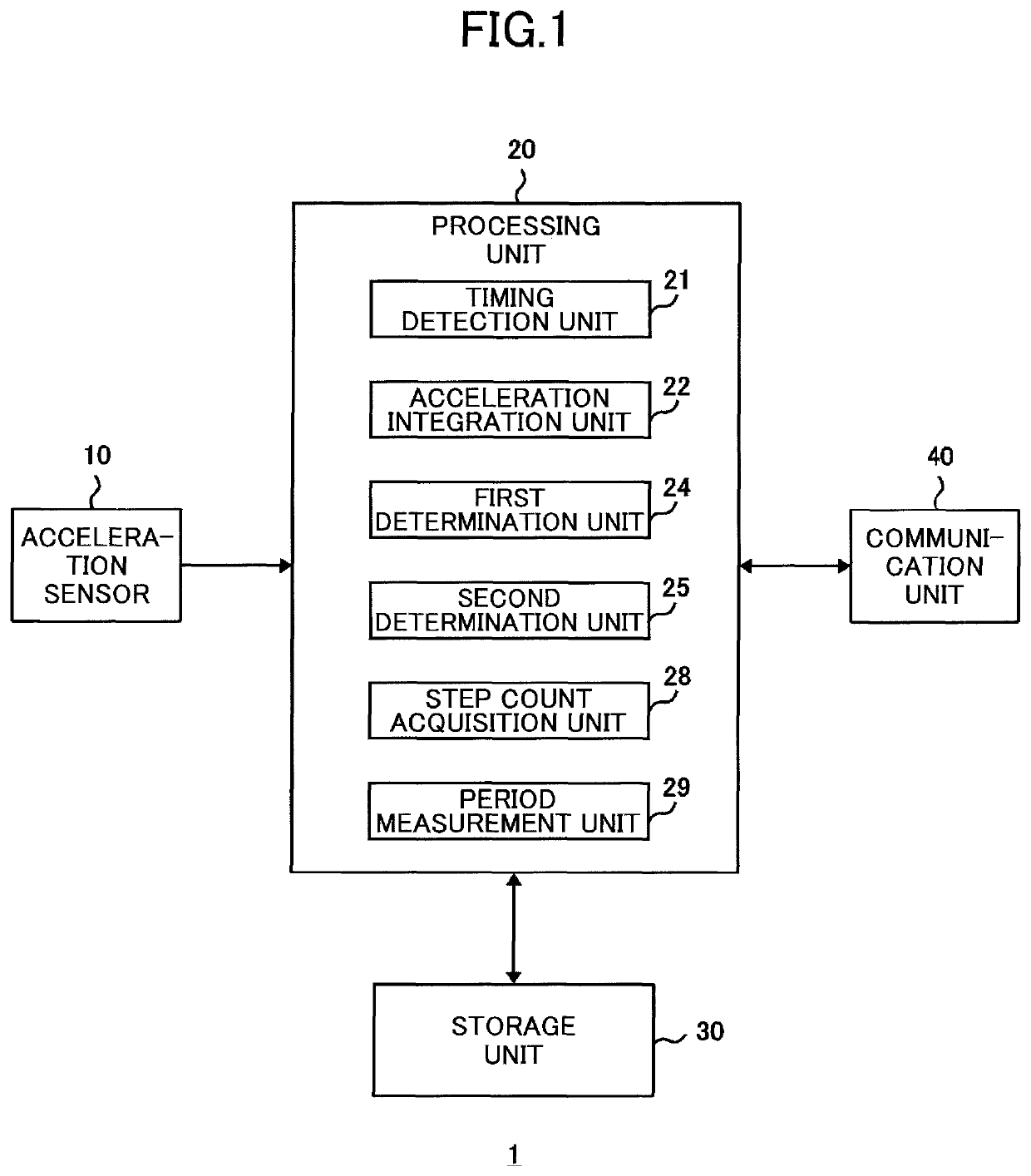
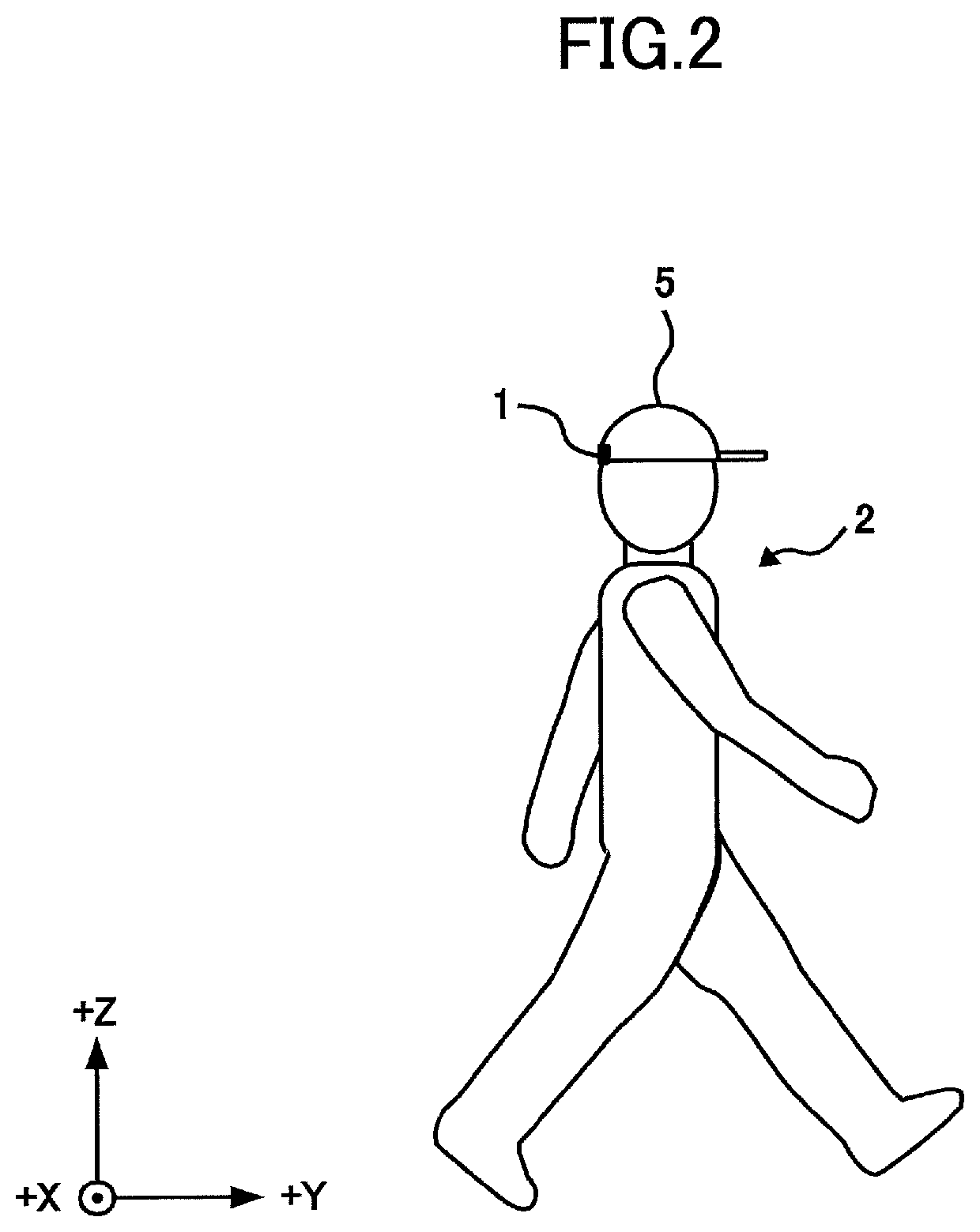
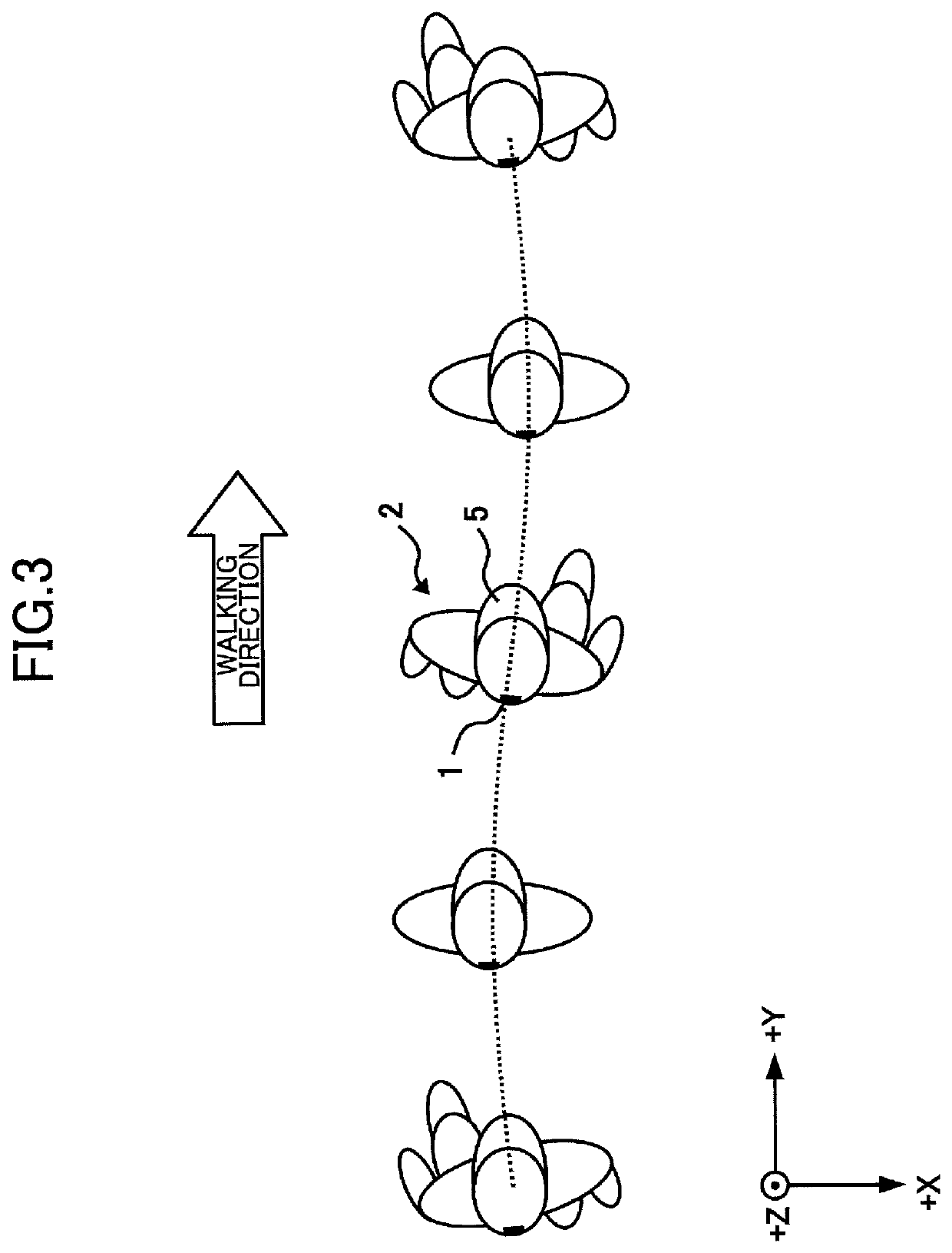
[0022]FIG. 1 is a diagram showing an example configuration of a walking measurement device 1 according to the present embodiment. FIG. 2 is a diagram showing an example method of mounting the walking measuring apparatus 1. FIG. 3 is a diagram illustrating lateral movements of the body in a walking motion. Note that in FIGS. 2 and 3, the Z-axis represents the vertical direction perpendicular to the ground, the X-axis represents the lateral direction along which the left foot and right foot are arranged side by side in the body, and the Y-axis represents the anterior-posterior direction of the body perpendicular to the Z-axis and the X-axis.
[0023]The walking measurement device 1 according to the present embodiment determines whether the left foot or the right foot has landed in a walking motion and determines the pe...
second embodiment
[0066]In the following, a second embodiment of the present invention will be described.
[0067]FIG. 8 is a diagram showing an example configuration of a walking measurement device lA according to the second embodiment. The walking measurement deice 1A shown in FIG. 8 differs from the walking measurement device 1 shown in FIG. 1 in that the acceleration integration unit 22 in the processing unit 20 is replaced by an acceleration averaging unit 23, and the first determination unit 24 is replaced by a first determination unit 24A. Note that other features of the walking measurement device 1A of FIG. 8 may be substantially identical to those of the walking measurement device 1 shown in FIG. 1.
[0068]The acceleration averaging unit 23 obtains an average value (average acceleration) of the lateral acceleration detected by the acceleration sensor 10. For example, the acceleration averaging unit 23 may calculate a moving average of the lateral acceleration over a time period in which the timin...
third embodiment
[0077]In the following, a third embodiment of the present invention will be described.
[0078]FIG. 11 is a diagram showing an example configuration of a walking measurement device 1B according to the third embodiment. In the walking measurement device 1B shown in FIG. 11, an angular velocity sensor 50 is added as an additional element to the walking measurement device 1 shown in FIG. 1, and a rotation angle calculation unit 26 and an acceleration conversion unit 27 are added as additional elements of the processing unit 20. Note that other features of the walking measurement device 1B shown in FIG. 11 may be substantially identical to those of the walking measurement device 1 shown in FIG. 1.
[0079]The angular velocity sensor 50 detects angular velocities along the three axes corresponding to the three directions of the accelerations detected by the acceleration sensor 10 (X-axis direction, Y-axis direction, Z-axis direction in FIGS. 2 and 3).
[0080]The rotation angle calculation unit 2...
PUM
 Abstract
Description
Claims
Application Information
 - R&D
- Intellectual Property
- Life Sciences
- Materials
- Tech Scout
- Unparalleled Data Quality
- Higher Quality Content
- 60% Fewer Hallucinations
Browse by: Latest US Patents, China's latest patents, Technical Efficacy Thesaurus, Application Domain, Technology Topic, Popular Technical Reports.
© 2025 PatSnap. All rights reserved.Legal|Privacy policy|Modern Slavery Act Transparency Statement|Sitemap|About US| Contact US: help@patsnap.com