
Clock faces for an electronic device

a clock face and electronic device technology, applied in the field of computer user interfaces, can solve the problems of cumbersome and inefficient technology of presenting and interacting with clock faces using electronic devices, complex and time-consuming user interfaces, and existing techniques that require more time than necessary, so as to improve efficiency, improve efficiency, and improve user satisfaction.

Active Publication Date: 2020-09-29
APPLE INC
View PDF545 Cites 27 Cited by
  • Summary
  • Abstract
  • Description
  • Claims
  • Application Information

AI Technical Summary

Benefits of technology

[0005]Accordingly, the present technique provides electronic devices with faster, more efficient methods and interfaces for presenting and interacting with clock faces. Such methods and interfaces optionally complement or replace other methods for presenting and interacting with clock faces. Such methods and interfaces reduce the cognitive burden on a user and produce a more efficient human-machine interface. For battery-operated computing devices, such methods and interfaces conserve power and increase the time between battery charges.
[0042]Thus, devices are provided with faster, more efficient methods and interfaces for presenting and interacting with clock faces, thereby increasing the effectiveness, efficiency, and user satisfaction with such devices. Such methods and interfaces may complement or replace other methods for presenting and interacting with clock faces.

Problems solved by technology

Some techniques for presenting and interacting with clock faces using electronic devices, however, are generally cumbersome and inefficient.
For example, some existing techniques use a complex and time-consuming user interface, which may include multiple key presses or keystrokes.
Existing techniques require more time than necessary, wasting user time and device energy.

Method used


Image

  • Clock faces for an electronic device
  • Clock faces for an electronic device
  • Clock faces for an electronic device

Examples


Embodiment Construction

[0068]The following description sets forth exemplary methods, parameters, and the like. It should be recognized, however, that such description is not intended as a limitation on the scope of the present disclosure but is instead provided as a description of exemplary embodiments.

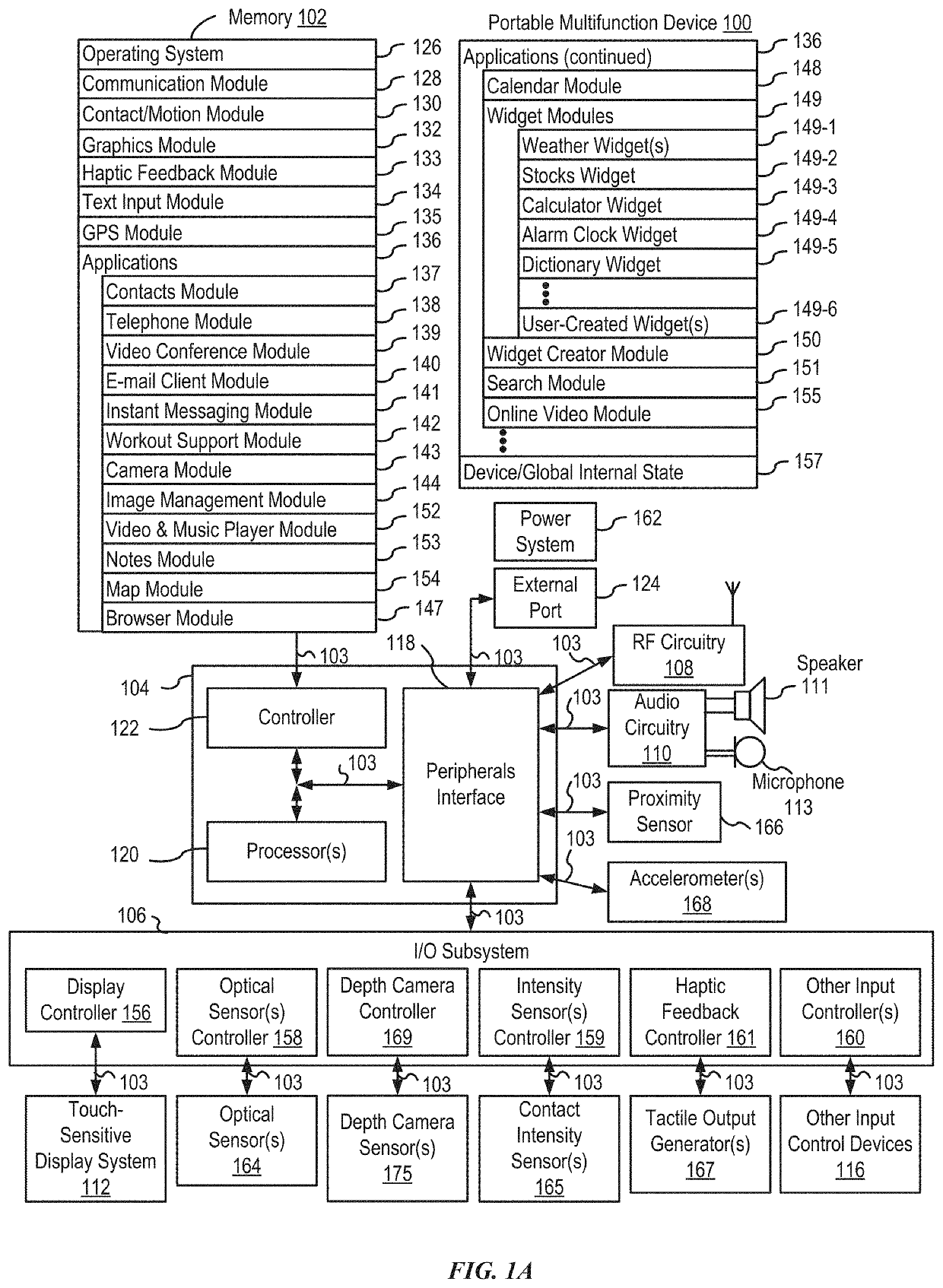
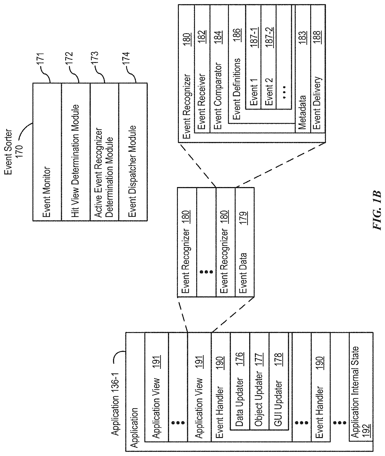
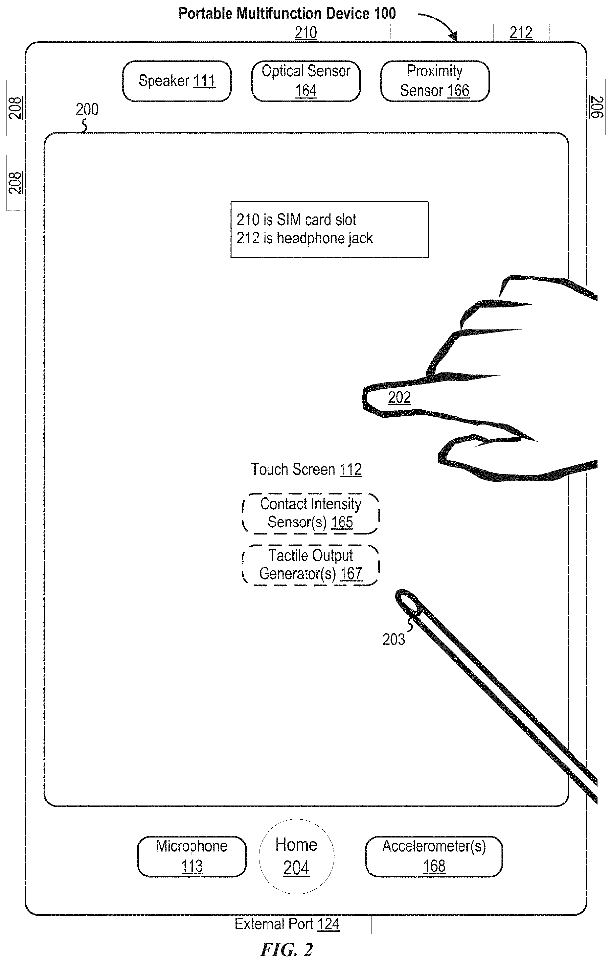
[0069]There is a need for electronic devices that provide efficient methods and interfaces for presenting and interacting with clock faces. According to some embodiments, an element of an analog dial of a clock face is displayed based on a determination of whether or not another graphical element (e.g., a notification or a complication) is to be displayed on the clock face. According to some embodiments, an indication of time is displayed according to a selected language while the language in which other graphical elements of a clock face (e.g., complications) are displayed is maintained. According to some embodiments, a device displays a clock face including a gradient that is displayed based on the positi...


PUM


Abstract

A device displays a clock face in response to receiving a request to display a clock face. In accordance with a determination that a respective graphical element is to be displayed at a respective location on the clock face, the clock face includes a plurality of analog-dial graphical elements corresponding to respective units of time, where the plurality of analog-dial graphical elements includes a first analog-dial graphical element that occupies a first position and has a first size. In accordance with a determination that the respective graphical element is not to be displayed at a respective location on the clock face, the clock face includes the plurality of analog-dial graphical elements corresponding to the respective units of time, and the first analog-dial graphical element of the plurality of analog-dial graphical elements occupies a second position and / or has a second size. In some embodiments, clock faces are reordered.

Description

CROSS-REFERENCE TO RELATED APPLICATIONS[0001]This application claims priority to U.S. Patent Application Ser. No. 62 / 844,108, entitled “CLOCK FACES FOR AN ELECTRONIC DEVICE”, filed on May 6, 2019, and U.S. Patent Application Ser. No. 62 / 856,038, entitled “CLOCK FACES FOR AN ELECTRONIC DEVICE”, filed on Jun. 1, 2019, the contents of all of which are hereby incorporated by reference in their entirety.FIELD[0002]The present disclosure relates generally to computer user interfaces, and more specifically to clock faces for electronic devices.BACKGROUND[0003]Users rely on portable multifunction devices for a variety of operations, including telling time. Such users may want to be provided with a current time along with other context-specific information.BRIEF SUMMARY[0004]Some techniques for presenting and interacting with clock faces using electronic devices, however, are generally cumbersome and inefficient. For example, some existing techniques use a complex and time-consuming user int...

Claims


Application Information

Patent Timeline
Patent Type & Authority Patents(United States)
IPC IPC(8): G06F3/0482G04G9/02G06F3/0488G06F3/0481G06F3/0483G06F1/16G04G9/00
CPCG06F3/0482G06F3/0481G06F3/04817G04G9/027G06F3/0483G06F3/0488G06F1/163G04G9/007G06F3/0414G06F3/04883G06F3/016G04G9/00G06F2203/04105G06F3/04845G04G9/0064G04G9/06G04G9/062G04G21/08G04G9/04G06F3/0362G06F3/04847G06F3/041
Inventor GUZMAN, AURELIOCHEN, KEVIN WILLWILSON, CHRISTOPHERWILSON, ERIC LANCEWEISS, JACOB Z.MORALES, JESUS A.TROTTIER, LAUREN KIM
Owner APPLE INC
Learn More