
Removable orthodontic correction device

a technology of orthodontic correction and removable brackets, which is applied in the field of orthodontic correction technology, can solve the problems of affecting the patient's oral health, and reducing the patient's comfort, and achieves the effect of effectively delivering bone remodeling pressur

Active Publication Date: 2020-08-04
HUNG CHENG HSIANG
View PDF21 Cites 3 Cited by
  • Summary
  • Abstract
  • Description
  • Claims
  • Application Information

AI Technical Summary

Benefits of technology

[0010]In view of the aforementioned problems, an object of the invention is to provide a patient removable orthodontic correction device which can be used to achieve en masse retraction and intrusion of the anterior teeth after the extraction of premolars in order to correct maxillary or bimaxillary protrusion. Another object of the invention is to achieve retraction of the anterior teeth as a single block and effectively deliver bone remodeling pressure to the region of space closure, which is the interproximal alveolar bone near the space left by the extracted premolar.
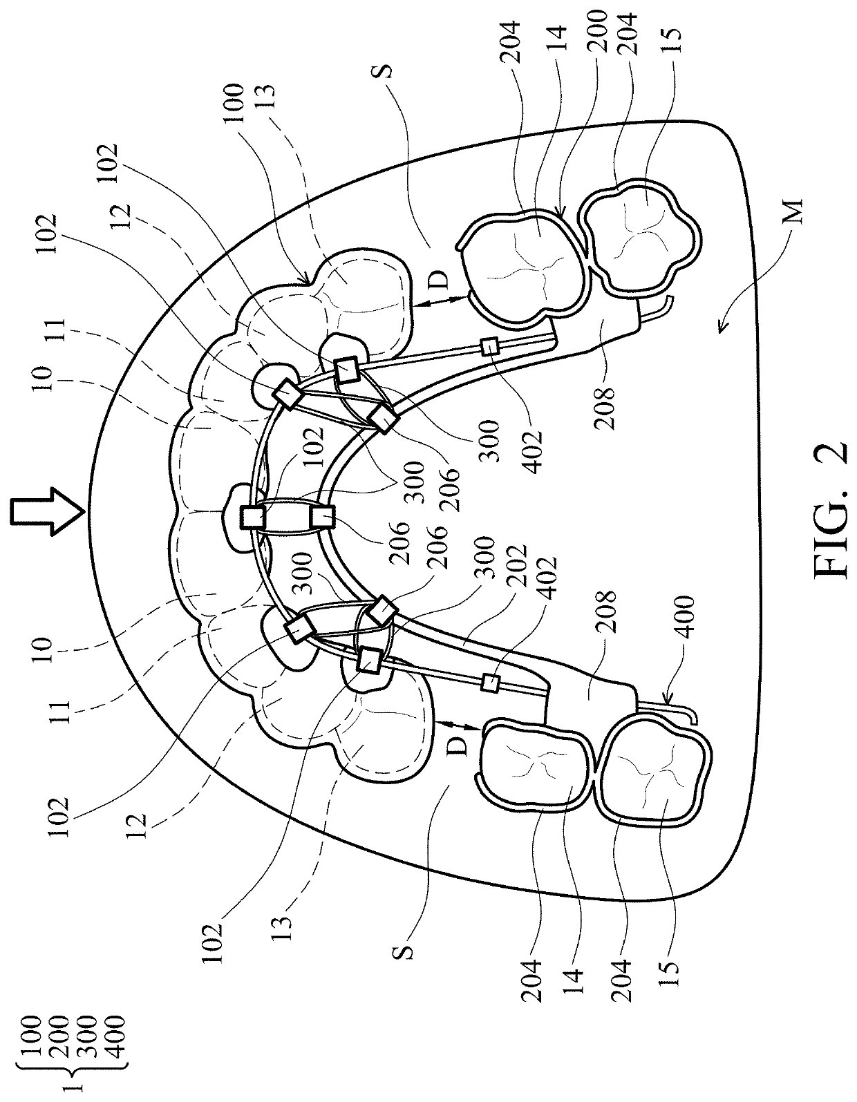
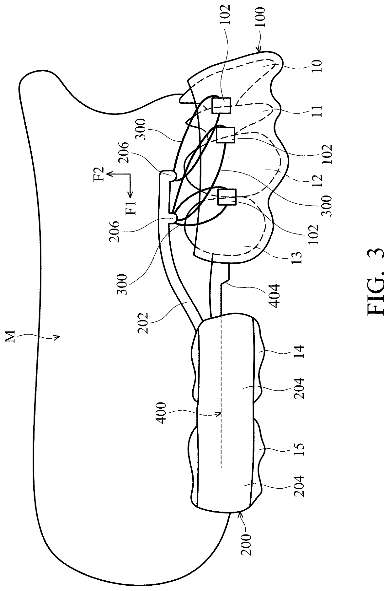
[0012]In some embodiments, the first connection parts are fixed on a lingual surface of the first correction unit. The second correction unit includes a first transverse part and several mounting parts connected to both ends of the first transverse part. The mounting parts at each end of the first transverse part are joined together and configured to be removably mounted on the posterior teeth. The first transverse part is displaced distally from the lingual surface of the first correction unit, and the first transverse part has a curved shape that matches the curvature of the anterior teeth. The anterior part of the first transverse part is elevated, almost touching the palate, or lowered, almost touching the floor of the mouth to increase stability and retention of the second correction unit. The second connection parts of the second correction unit are fixed on the first transverse part or the mounting parts.
[0013]In some embodiments, the second correction unit further includes a second transverse part which is also connected to the mounting parts, but is displaced distally from the first transverse part. The second transverse part has a curved shape, almost touching the palate of the patient, so as to increase stability and retention of the second correction unit.
[0024]In some embodiments, the mounting parts each have a thickened structure formed on an occlusal surface thereof, so as to increase the vertical separation between the second correction unit and the opposing dental arch with no correction unit. In cases of deep overbite where the mandibular incisors may obstruct the distal movement of the maxillary incisors, increasing the vertical dimension facilitates the retraction of the maxillary anterior teeth during space closure.

Problems solved by technology

Misaligned teeth can adversely affect a person's dental aesthetics, functions, and health.
The space closure step is a challenge, calling for an effective mechanism to achieve smooth retraction of the anterior teeth.
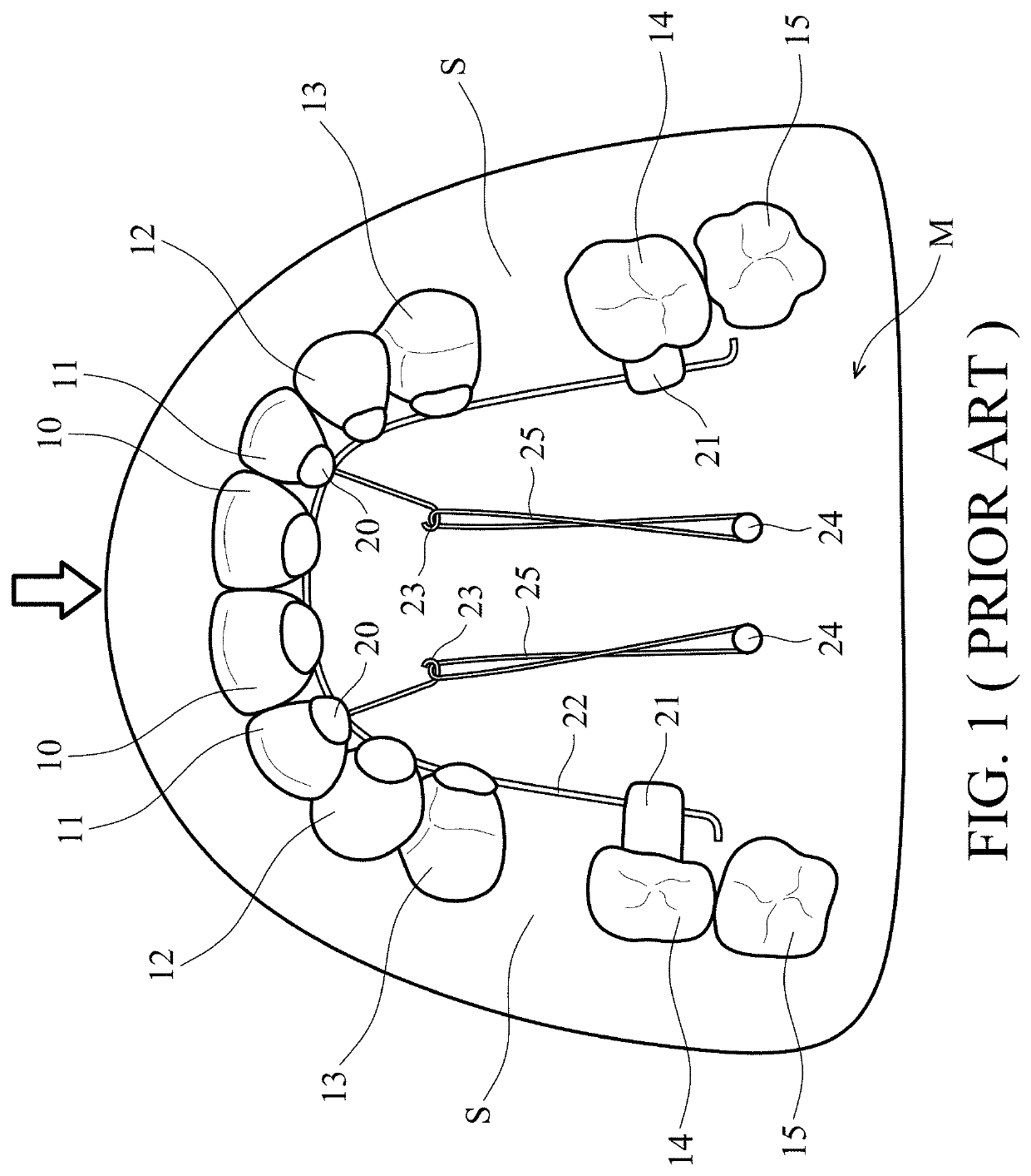
However, while using the orthodontic correction device described above, the mini-screws implants 24 are implanted in the palate of the maxilla M. This is an invasive procedure which can cause local inflammation, and the presence of the implants can restrict tongue motion and cause discomfort to the patient during space closure.
In addition, debonding of brackets and the removal of adhesive or resin debris from the enamel surface can cause damage to the tooth enamel.

Method used


Image

  • Removable orthodontic correction device
  • Removable orthodontic correction device
  • Removable orthodontic correction device

Examples


Embodiment Construction

[0039]In order to illustrate the purposes, features, and advantages of the invention, the preferred embodiments and drawings of the invention are shown in detail as follows.

[0040]In the following detailed description, the orientations of “on”, “above”, “under”, “below”, “left”, “right”, “anterior” and “posterior” are used for representing the relationship between the relative positions of each element as illustrated in the drawings, and are not meant to limit the invention.

[0041]In addition, the present disclosure may repeat reference numerals and / or letters in the various examples. This repetition is for the purpose of simplicity and clarity and does not in itself dictate a relationship between the various embodiments and / or configurations discussed. Various features may be arbitrarily drawn in different scales for the sake of simplicity and clarity.

[0042]FIG. 2 is a schematic view illustrating a removable orthodontic correction device 1 in accordance with an embodiment of the inve...


PUM


Abstract

A removable orthodontic correction device includes a first correction unit, a second correction unit, and several elastic members. The first correction unit is configured to be removably worn on the anterior teeth of the maxillary or mandibular dental arch of a patient and has several first connection parts formed thereon. The second correction unit is configured to be removably worn on the posterior teeth of the same maxillary or mandibular dental arch of the patient and has several second connection parts formed thereon. The elastic members couple the first connection parts to the second connection parts. Thus, the elastic force of the elastic members drives the first correction unit to retract toward the second correction unit, to achieve en masse retraction and intrusion of the anterior teeth during space closure in the treatment of dental protrusion.

Description

CROSS REFERENCE TO RELATED APPLICATIONS[0001]The present application claims priority of China Patent Application No. 201610132939.2, filed on Mar. 9, 2016, the entirety of which is incorporated by reference herein.BACKGROUND OF THE INVENTION[0002]Field of the Invention[0003]The present application relates to an orthodontic correction technology; and in particular to a removable orthodontic correction device.[0004]Description of the Related Art[0005]Misaligned teeth can adversely affect a person's dental aesthetics, functions, and health. The goal of orthodontic correction is to bring the teeth into proper alignment by using appliances which exert mechanical forces to move the teeth to positions or orientations where the dental functions and aesthetics are improved.[0006]Dental protrusion is a common condition requiring orthodontic treatment. Dentoalveolar protrusion of the maxillary or both the maxillary and mandibular (bimaxillary) anterior teeth results in a convex facial profile....

Claims


Application Information

Patent Timeline
Patent Type & Authority Patents(United States)
IPC IPC(8): A61C7/08A61C7/10A61C7/20A61C7/14
CPCA61C7/10A61C7/20A61C7/08A61C7/145A61C7/00
Inventor HUNG, CHENG-HSIANG
Owner HUNG CHENG HSIANG
Learn More