Tire air filling mechanism and tire air filling method for tire testing device
a tire air filling and tire technology, which is applied in the direction of tyre repairing, tire measurement, vehicle components, etc., can solve the problems of air pressure dropping, difficult to secure the quality of a testing device or a testing line, and the stability of repeated use of a testing device cannot be sure determined, so as to reduce the fluctuation of air pressure, reduce the cost, and reduce the effect of air filling
- Summary
- Abstract
- Description
- Claims
- Application Information
AI Technical Summary
Benefits of technology
Problems solved by technology
Method used
Image

Examples
first embodiment
[0037]First, a tire testing device 2 provided with a tire air filling mechanism 1 according to the invention will be described below in detail with reference to the drawings.
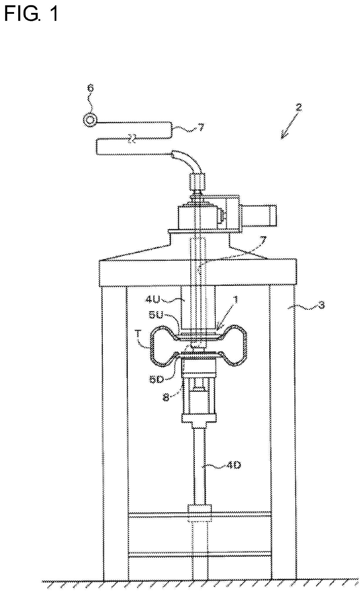
[0038]FIG. 1 schematically illustrates the tire testing device 2 provided with the tire air filling mechanism 1 according to a first embodiment.
[0039]The tire testing device 2 is generally called a tire uniformity machine, which performs product testing such as tire uniformity on a tire T finished as a product. The tire testing device 2 has a configuration illustrated in FIG. 1 by way of example.
[0040]As schematically illustrated in FIG. 1, the tire testing device 2 includes a frame 3 provided on a floor like a tower, a pair of upper and lower tire shafts 4U and 4D attached to the frame 3, and a pair of upper and lower rims 5U and 5D provided on the tire shafts 4U and 4D so as to fix the tire T. The rims 5U and 5D are disposed rotatably around the tire shafts 4U and 4D facing in an up / down direction. Further, a ...
second embodiment
[0074]Next, a tire air filling mechanism 1 according to a second embodiment will be described with reference to the drawings.
[0075]As illustrated in FIG. 4A and FIG. 4B, the tire air filling mechanism 1 according to the second embodiment is provided with tube members 18 which are curved so that the injection direction of the air injected in a radial direction from each air injection port 8 can be changed to a direction inclined with respect to the radial direction.
[0076]Specifically, each tube member 18 is a hollow member (tube) extending from the aforementioned air supply flow path 7 to the radially outside. The air can be circulated inside the tube member 18. An inner circumferential side end portion of the tube member 18 is coupled with the tire shaft 4U so that the air can be introduced from the air supply flow path 7. An outer circumferential side end portion of the tube member 18 is located on the inner circumferential side of the rim 5U so that the tube member 18 can be preve...
third embodiment
[0078]Next, a tire air filling mechanism 1 according to a third embodiment will be described with reference to the drawings.
[0079]As illustrated in FIG. 5A and FIG. 5B, the tire air filling mechanism 1 according to the third embodiment is provided with direction-changing plates 19 by which the injection direction of the air injected in a radial direction from each air injection port 8 can be changed to a direction inclined with respect to the radial direction.
[0080]Specifically, in the tire shaft 4U where the tire air filling mechanism 1 according to the third embodiment is provided, air injection ports 8 are formed along a radial direction of the tire shaft 4U in the same manner as in the other embodiments. The air is injected in the radial direction from the air injection ports 8. However, in the tire air filling mechanism 1 according to the third embodiment, the direction-changing plates 19 are provided on the radially outside of the air injection ports 8 so that the flow of the ...
PUM
 Abstract
Description
Claims
Application Information
 - Generate Ideas
- Intellectual Property
- Life Sciences
- Materials
- Tech Scout
- Unparalleled Data Quality
- Higher Quality Content
- 60% Fewer Hallucinations
Browse by: Latest US Patents, China's latest patents, Technical Efficacy Thesaurus, Application Domain, Technology Topic, Popular Technical Reports.
© 2025 PatSnap. All rights reserved.Legal|Privacy policy|Modern Slavery Act Transparency Statement|Sitemap|About US| Contact US: help@patsnap.com