Particulate-filled adaptive capsule (PAC) charge

a technology of adaptive capsules and charged particles, applied in the field of shaped charges, can solve the problem that the shape change cannot be adapted in the field to change the application requirements,

Active Publication Date: 2020-06-16
THE UNITED STATES OF AMERICA AS REPRESENTED BY THE SECRETARY OF THE NAVY
View PDF43 Cites 11 Cited by
  • Summary
  • Abstract
  • Description
  • Claims
  • Application Information

AI Technical Summary

Problems solved by technology

Accordingly, such shaped changes cannot be adapted in the field for changing application requirements.

Method used


Image

  • Particulate-filled adaptive capsule (PAC) charge
  • Particulate-filled adaptive capsule (PAC) charge
  • Particulate-filled adaptive capsule (PAC) charge

Examples


Embodiment Construction

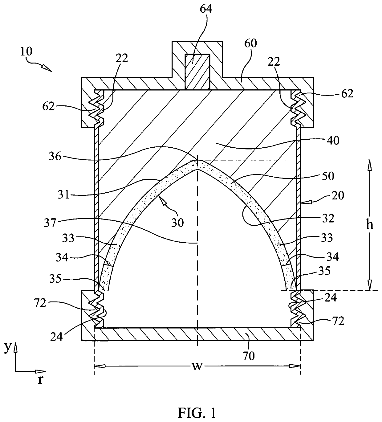
[0012]Referring now to the drawings and more particularly to FIG. 1, a shaped charge capable of creating a constant-diameter penetration hole is shown and is referenced generally by numeral 10. By way of an exemplary embodiment, the design of shaped charge 10 lends itself to assembly and adaptation in a field setting thereby allowing a user to customize the shaped charge to satisfy the requirements of a particular application. However, it is to be understood that the novel features of the present invention could be incorporated into other fabrication designs such as those assembled in a factory prior to deployment in the field.

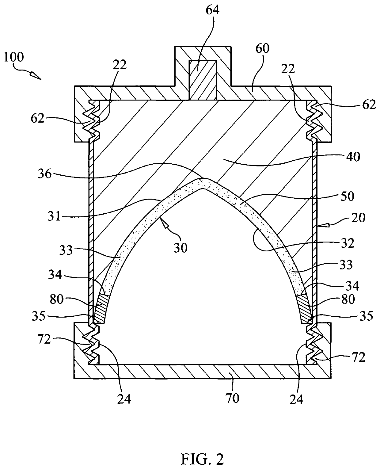
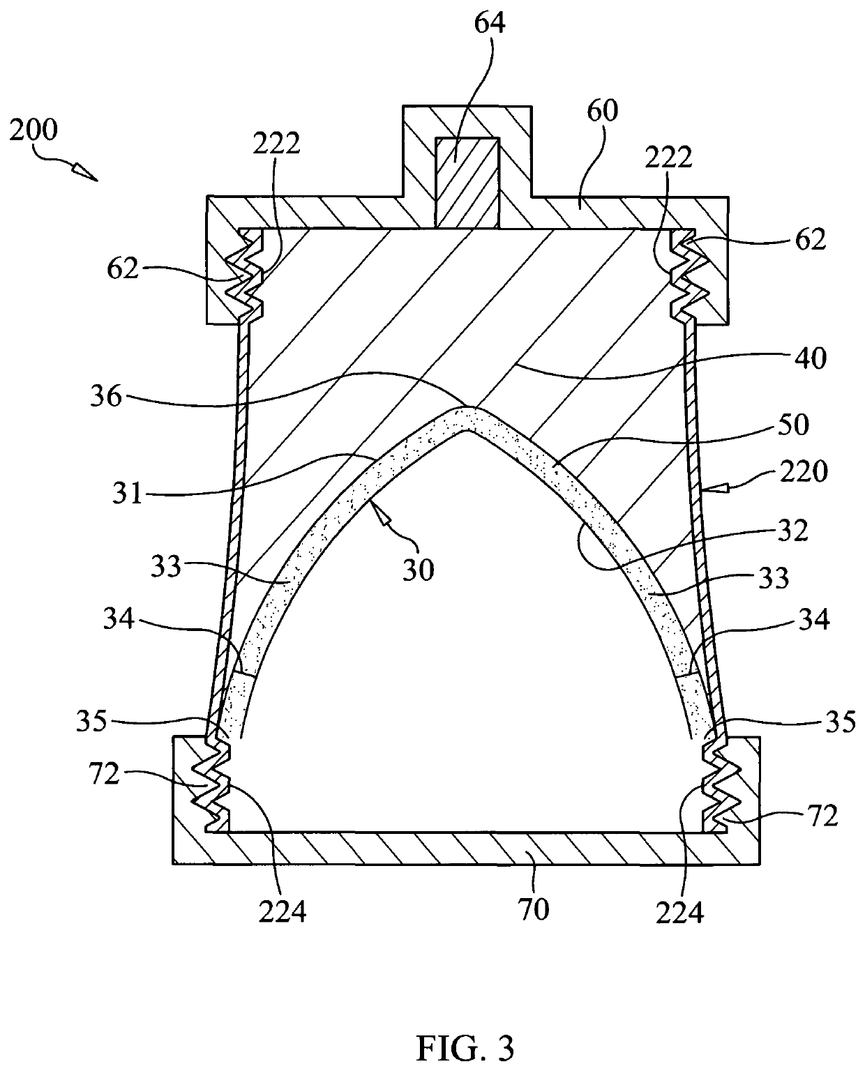
[0013]Shaped charge 10 includes a casing 20, a hollow and shaped liner 30, an explosive material 40 disposed in a portion of casing 20, a loose particulate material 50 disposed within liner 30, a blasting cap 60 coupled to one axial end of casing 20, and a sealing cap 70 coupled to the other axial end of casing 20. Descriptions of the various elements of shape...


PUM


Abstract

A shaped charge includes a casing with a liner disposed therein. The liner has two spaced-apart and nested walls with each wall having an identical ogive shape. An explosive material fills a portion of the casing up to one of the walls. A loose particulate material is disposed between the walls. A blasting cap is coupled to a first axial end of the casing adjacent to the explosive material, and a sealing cap is coupled to a second axial end of the casing.

Description

ORIGIN OF THE INVENTION[0001]The invention described herein was made in the performance of official duties by employees of the Department of the Navy and may be manufactured, used, licensed by or for the Government for any governmental purpose without payment of any royalties thereon.FIELD OF THE INVENTION[0002]The invention relates generally to shaped charges and more particularly to a shaped charge having an ogive-shaped liner to provide penetration holes of constant diameter.BACKGROUND OF THE INVENTION[0003]Shaped charges are typically used to maximize penetration depth into and / or through armor or a structure. Traditional shaped charges incorporate a shaped, compressed liner within a casing that houses an explosive material. In general, penetration depth increases with increased liner density, while a penetration hole's diameter decreases with penetration depth. While designers of such shaped charges are usually unconcerned with diameter changes of the hole created by the penetr...

Claims


Application Information

Patent Timeline
Patent Type & Authority Patents(United States)
IPC IPC(8): F42B1/028E21B43/117F42B1/032
CPCE21B43/117F42B1/032F42B1/028
Inventor MCCARTHY, DANIELFOLTZ, LEEDIAZ, ANGELRIVERA MARCHAND, DAVID
Owner THE UNITED STATES OF AMERICA AS REPRESENTED BY THE SECRETARY OF THE NAVY
Why Eureka
Try Eureka