
Effector power adapter and effector working system

a technology of effector and working system, which is applied in the field of acoustic and musical instruments, can solve the problems of affecting the output of electrical signals of effectors and the difficulty of users to obtain the timbre desired by users, and achieve the effects of improving the integration level of products, enhancing the multifunctionality of voltage output ports, and enriching playing effects

Active Publication Date: 2020-05-26
SWIFF TECH CO LTD
View PDF4 Cites 0 Cited by
  • Summary
  • Abstract
  • Description
  • Claims
  • Application Information

AI Technical Summary

Benefits of technology

The present invention is an Effector Power Adapter that can output a continuous range of voltage through a voltage transformation output port. This allows users to adjust the voltage to meet the requirements of different effectors, resulting in different timbre and enriched playing effects. The multifunction and integration level of the product are improved by the output of different constant voltages through a single voltage output port and the silica gel sheath's function as a buffer and protector against dust and water penetration. The hand-holding portion prevents staining and damage to the power supply ports and the multiple electrical signal output ports. The effector working system described in this patent provides timbre, versatility, and a long service life.

Problems solved by technology

However, the electrical parameters of the internal electronic members of an effector slight change during the use of the effector, which affects the output of electrical signals of the effector.
Thus, changes of the electrical signals of the effector make it difficult to obtain the timbre desired by users.

Method used


Image

  • Effector power adapter and effector working system
  • Effector power adapter and effector working system
  • Effector power adapter and effector working system

Examples


Embodiment Construction

[0023]In order to illustrate the objects, technical solutions and advantages of the present invention more clearly, detailed description is made to the present invention with reference to the accompanying drawings and embodiments. It should be understood that the specific embodiments described herein are only intended to illustrate rather than limit the present invention.

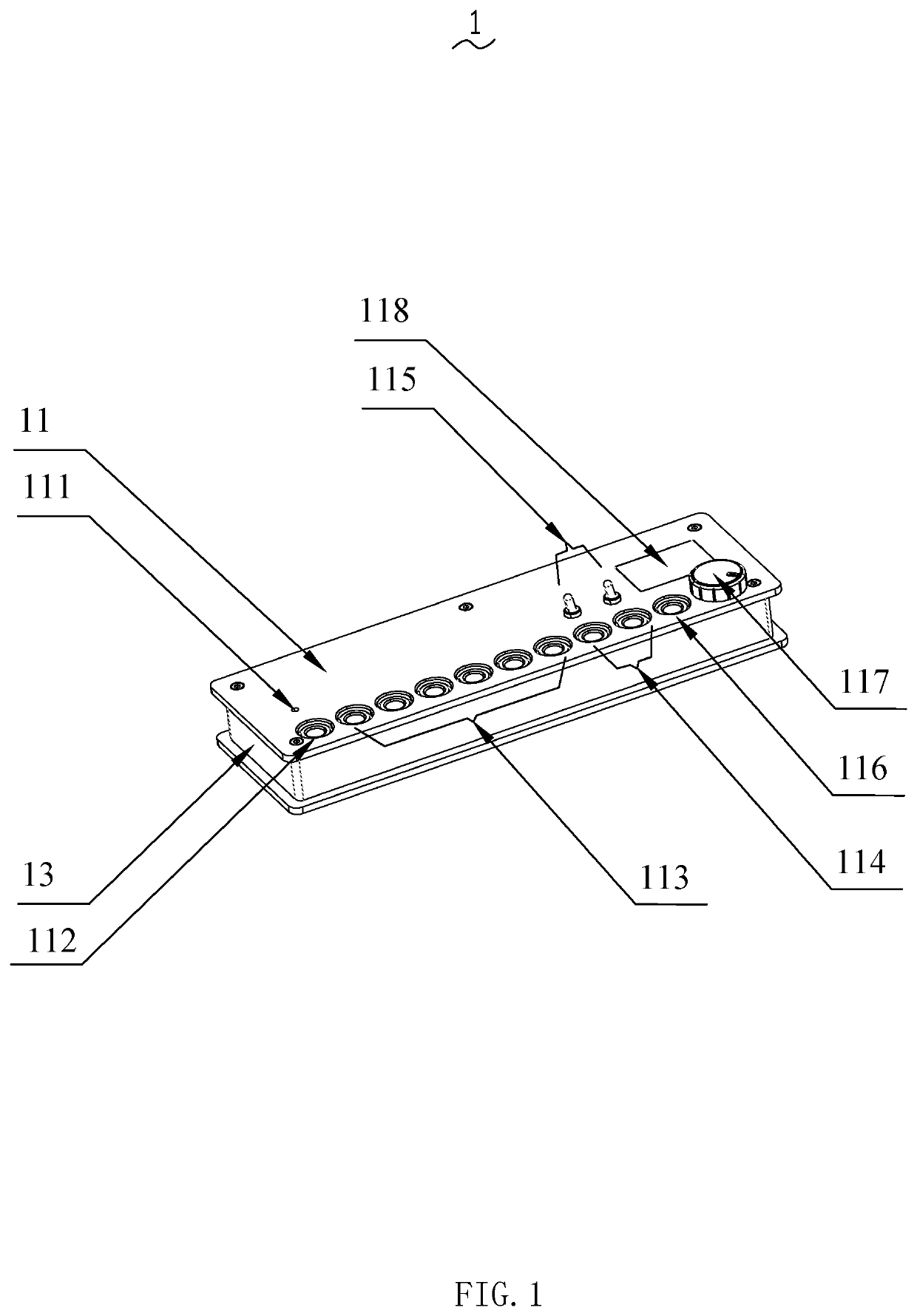
[0024]Referring to FIG. 1, the present invention provides an effector power adapter 1, whose one end is connected to a power source and whose other end to an effector. The power source supplies power to the effect via the effector power adapter 1.

[0025]The effector power adapter 1 includes a box cover 11 and a box body 13. The inside of the box body 13 is a chamber, which is covered by the box cover 11 snap-fits the box body 13 (in all the embodiments, the positional terms, such as “upper”, “lower”, “left”, “right”, “inside” and “outside”, only mean the relative positions in the drawings rather than absolute positio...


PUM


Abstract

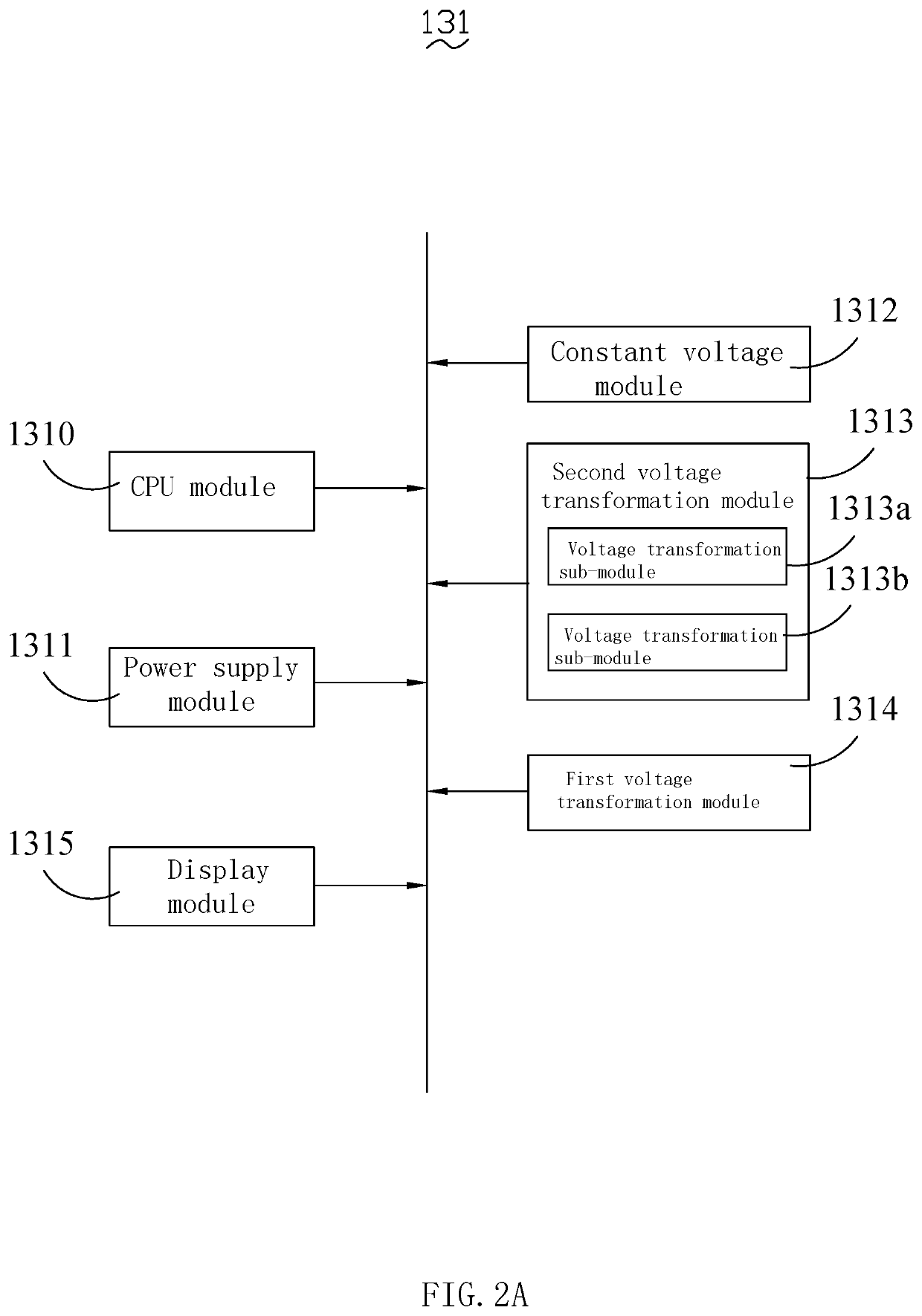
The present invention provides an Effector Power Adapter for connecting an effector, the Effector Power Adapter includes a power supply module, at least one first voltage transformation module and multiple voltage output ports, wherein the voltage output port has at least one first voltage transformation output port. The first voltage transformation module is electrically connected to the power supply module and the first voltage transformation output port, and the first voltage transformation module controls the first voltage transformation output port to output numerically continuously adjustable voltages. The present invention further provides an Effector Working System, which has an effector and the above effector power adapter. The Effector Power Adapter and the Effector Working System provided by the present invention can apply different voltages to an effector to produce different sound effects, which enriches the playing effect and offers more musical creation space for music practitioners.

Description

RELATED APPLICATIONS[0001]This application claims benefit to China Patent Application No. CN2016211099782, filed Oct. 9, 2016; and China Patent Application No. CN2017200783123, filed Jan. 21, 2017.[0002]The above applications and all patents, patent applications, articles, books, specifications, other publications, documents, and things referenced herein are hereby incorporated herein in their entirety for all purposes. To the extent of any inconsistency or conflict in the definition or use of a term between any of the incorporated publications, documents, or things and the text of the present document, the definition or use of the term in the present document shall prevail.BACKGROUND OF THE INVENTIONField of Invention[0003]The present invention is related to the field of acoustic and musical instruments, and more particularly to an effector power adapter and an effector working system.Related Art[0004]Stringed instruments are an important branch of musical instruments, and, thanks ...

Claims


Application Information

Patent Timeline
Patent Type & Authority Patents(United States)
IPC IPC(8): G10H1/00H01R13/66H01R25/00
CPCG10H1/0091H01R25/00G10H1/0008H01R13/665G10H2230/035G10H2210/155G10H2220/091
Inventor JIA, HE
Owner SWIFF TECH CO LTD
Learn More