
Display interface with foveal compression

a technology of foveal compression and display interface, which is applied in the direction of optics, electrical appliances, instruments, etc., can solve the problems of limited rate at which the hmd device can display new images to the user, and achieve the effect of limiting the scope of the claimed subject matter

Active Publication Date: 2020-05-26
SYNAPTICS INC
View PDF5 Cites 1 Cited by
  • Summary
  • Abstract
  • Description
  • Claims
  • Application Information

AI Technical Summary

Benefits of technology

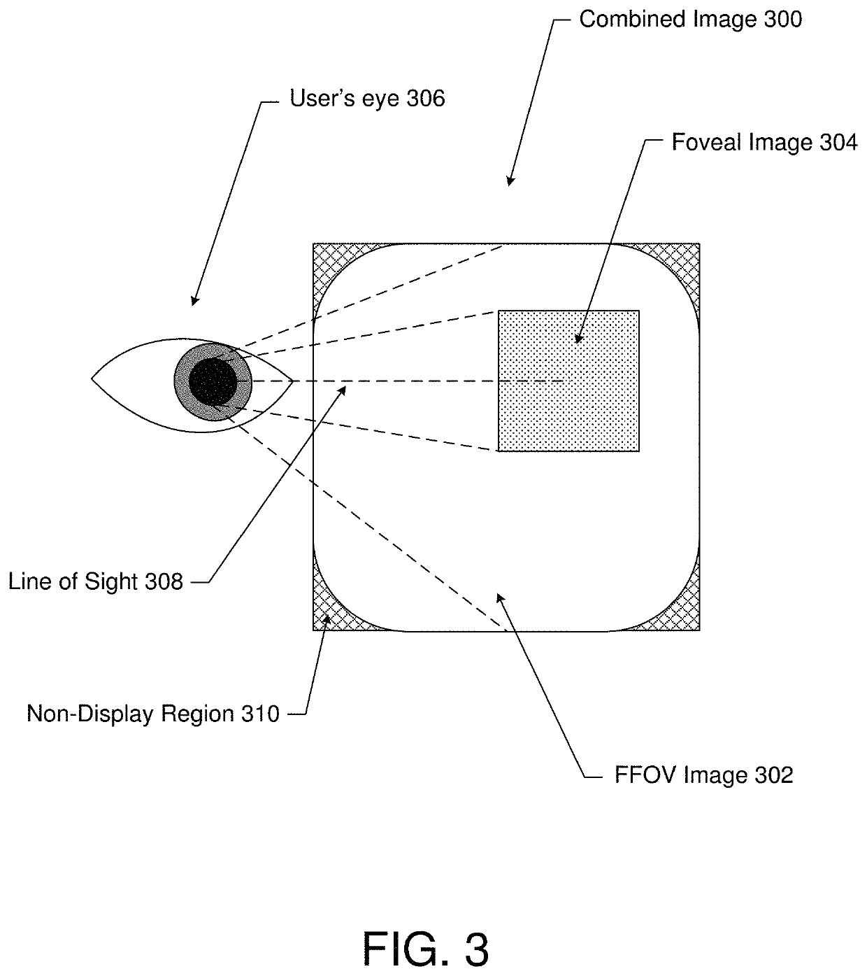
The patent describes a method for transporting foveal image data, which is image data that is processed by the foveal region of the visual cortex. This region allows for highly detailed image processing, so the foveal image data is of higher resolution than the surrounding field-of-view (FOV) image. The host device receives the foveal image data and the FOV image, and identifies the foveal region in the FOV image. The host then creates a frame buffer image with higher resolution than the FOV image and transmits it to a display device. The host can also transmit the coordinate of the foveal region to the display device. This allows for precise positioning of the foveal image and ensures that it is aligned with the FOV image. The technical effect of this patent is to provide a more efficient and accurate way for displaying foveal image data.

Problems solved by technology

Because the host device is physically separated from the HMD device, the rate at which the HMD device can display new images to the user is often limited by the bandwidth of the communication medium (e.g., cable) connecting the host device to the HMD device.

Method used


Image

  • Display interface with foveal compression
  • Display interface with foveal compression
  • Display interface with foveal compression

Examples


Embodiment Construction

[0024]In the following description, numerous specific details are set forth such as examples of specific components, circuits, and processes to provide a thorough understanding of the present disclosure. The term “coupled” as used herein means connected directly to or connected through one or more intervening components or circuits. The terms “electronic system” and “electronic device” may be used interchangeably to refer to any system capable of electronically processing information. Also, in the following description and for purposes of explanation, specific nomenclature is set forth to provide a thorough understanding of the aspects of the disclosure. However, it will be apparent to one skilled in the art that these specific details may not be required to practice the example embodiments. In other instances, well-known circuits and devices are shown in block diagram form to avoid obscuring the present disclosure. Some portions of the detailed descriptions which follow are present...


PUM


Abstract

A method of transporting foveal image data is disclosed. A host device receives image data from an image source and renders a full field-of-view (FFOV) image using the image data. The host device further identifies a foveal region of the FFOV image and renders a foveal image corresponding to the foveal region using the image data. More specifically, the foveal image may have a higher resolution than the foveal region of the FFOV image. The host device may then transmit each of the foveal image and the FFOV image, in its entirety, to a display device. For example, the host device may concatenate the foveal image with the FFOV image to produce a frame buffer image, and then transmit the frame buffer image to the display device.

Description

CROSS-REFERENCE TO RELATED APPLICATIONS[0001]The present application is a U.S. National Stage under 35 U.S.C. § 371 of International Application No. PCT / US2018 / 033551 filed May 18, 2018 entitled “DISPLAY INTERFACE WITH FOVEAL COMPRESSION,” which claims priority to U.S. Provisional Patent Application No. 62 / 508,240 filed May 18, 2017 entitled “DISPLAY INTERFACE WITH FOVEAL COMPRESSION.” The entire contents of which are incorporated herein by reference.TECHNICAL FIELD[0002]The present embodiments relate generally to head-mounted display (HMD) devices, and specifically to a display interface with foveal compression for HMD devices.BACKGROUND OF RELATED ART[0003]Head-mounted display (HMD) devices are configured to be worn on, or otherwise affixed to, a user's head. An HMD typically comprises one or more displays positioned in front of one, or both, of the user's eyes. The HMD may display images (e.g., still images, sequences of images, and / or videos) from an image source overlaid with i...

Claims


Application Information

Patent Timeline
Patent Type & Authority Patents(United States)
IPC IPC(8): G09G5/391G09G5/00H04N13/383G02B27/01H04N13/344G09G5/377
CPCG09G5/391H04N13/383H04N13/344G02B27/017G09G5/377G09G5/006G09G2340/10G09G2354/00G02B2027/0147G09G2360/18G09G2340/0407G02B2027/0187G09G2340/12
Inventor MOREIN, STEPHEN L.
Owner SYNAPTICS INC
Learn More