System and method for measuring body joint range of motion

Active Publication Date: 2020-05-12
SHARP KK
View PDF4 Cites 0 Cited by
  • Summary
  • Abstract
  • Description
  • Claims
  • Application Information

AI Technical Summary

Benefits of technology

The system described in this patent allows for easy measurement of the movement of body joints using an inertial measurement unit (IMU) attached to the body segments connected by the joint. The results are reported back to medical staff or other interested parties for monitoring. The user interface adapts to the specific joint being measured and is based on physiologically modeled quaternion joint rotation decomposition. This system provides a more accurate and stable measurement of the range of motion compared to Euler angles, but is still easily understandable for medical personnel and patients.

Problems solved by technology

Often the patient does not understand or correctly comply with the doctor's recovery instructions, and upon returning to their home, the patient is not sufficiently monitored by medical staff to determine if recovery is proceeding well.
This lack of monitoring may result in poor RoM and the need for additional surgeries.
Currently existing systems do not use physiologically modeled joint rotation decomposition to determine constituent joint rotations.
They also are only capable of displaying a single planar rotation, and cannot calculate or display each of the constituent rotations that makeup the composite rotation.
They do not automatically adapt their analysis to the specific joints that are being measured.
They are not able to send trending information to remote viewers.

Method used


Image

  • System and method for measuring body joint range of motion
  • System and method for measuring body joint range of motion
  • System and method for measuring body joint range of motion

Examples


Embodiment Construction

[0023]The systems and methods described herein use the notation, concepts, and techniques described in the following applications, which are incorporated herein by reference:

[0024]Ser. No. 14 / 873,946, entitled, SYSTEM AND METHOD FOR DETERMINING THE ORIENTATION OF AN INERTIAL MEASUREMENT UNIT (IMU), filed Oct. 2, 2015;

[0025]Ser. No. 15 / 091,869, entitled, SYSTEM AND METHOD FOR DETERMINING ORIENTATION OF BODY SEGMENTS USING INERTIAL MEASUREMENT UNITS, filed Apr. 6, 2016;

[0026]Ser. No. 14 / 742,852, SENSOR CALIBRATION METHOD AND SYSTEM, filed Jun. 18, 2015; and,

[0027]Ser. No. 14 / 707,194, METHOD AND SYSTEM FOR WIRELESS TRANSMISSION OF QUATERNIONS, filed May 8, 2015.

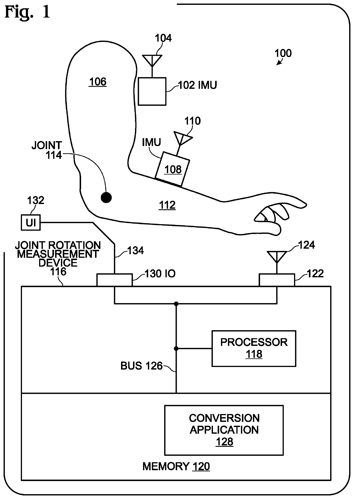
[0028]FIG. 1 is a schematic block diagram of system for measuring body joint range of motion using inertial measurement unit (IMU) sensors capable of measuring their orientation relative to Earth. The system 100 comprises a primary IMU sensor 102, having a wireless interface 104, mounting on a proximal body segment 106. A second...


PUM


Abstract

A system and method are provided for measuring body joint range of motion using inertial measurement unit (IMU) sensors capable of measuring their orientations relative to Earth. The method mounts a primary IMU sensor on a proximal body segment, and a secondary IMU sensor on a distal body segment connected to the proximal body segment via a joint. The sensor orientation relationship is measured between the primary IMU sensor and the secondary IMU sensor. In one aspect, the sensor orientation relationship is expressed as a quaternion. The sensor orientation relationship is converted into at least one physiologically modeled constituent joint rotation relationship between the proximal body segment and the distal body segment. More explicitly, the sensor orientation relationship is converted to a constituent axial axis, composite radial, or primary and secondary radial rotations of the distal body segment measured with respect to the proximal body segment.

Description

BACKGROUND OF THE INVENTION[0001]1. Field of the Invention[0002]This invention generally relates to human body joint motion evaluation and, more particularly, to a system and method for converting inertial measurement unit (IMU) sensor measurements into physiologically defined joint rotation measurements in a standard format more easily understood by health care professionals.[0003]2. Description of the Related Art[0004]Measuring a body joint's range of motion (RoM) is critical for applications such as joint surgery recovery and sports technique coaching. It is also important for orthopedic patients to begin flexing the repaired joint soon after surgery is completed. Often the patient does not understand or correctly comply with the doctor's recovery instructions, and upon returning to their home, the patient is not sufficiently monitored by medical staff to determine if recovery is proceeding well. This lack of monitoring may result in poor RoM and the need for additional surgeries...

Claims


Application Information

Patent Timeline
IPC IPC(8): A61B5/00A61B5/11
CPCA61B5/1121A61B5/742A61B5/4528A61B5/1114A61B5/7475A61B2562/0219A61B5/0024
Inventor HALLBERG, BRYAN
Owner SHARP KK
Why Eureka
Try Eureka