
Back light module and display device

a backlight module and display device technology, applied in the field of backlight modules, can solve the problems that the frame structure does not meet the design trend of narrow borders, and achieve the effects of increasing the carrying area of the display panel, increasing the frame border width, and increasing the reliability of holding the display panel

Active Publication Date: 2020-05-05
RADIANT OPTO ELECTRONICS SUZHOU +1
View PDF21 Cites 0 Cited by
  • Summary
  • Abstract
  • Description
  • Claims
  • Application Information

AI Technical Summary

Benefits of technology

[0020]From the aforementioned embodiments of the present invention, it can be known that the first carrying portion is disposed on the sidewall of the back plate, such that the display panel is firmly held on the first carrying portion and the sidewall of the back plate. Moreover, the optical film has the notch used to receive the first carrying portion, thereby increasing the carrying area of the display panel without needing to increase the frame border width or affecting the area of the display area, thus increasing the reliability of holding the display panel on the back plate.

Problems solved by technology

However, this mold frame structure does not meet the design trend of narrow border display device.

Method used


Image

  • Back light module and display device
  • Back light module and display device
  • Back light module and display device

Examples


first embodiment

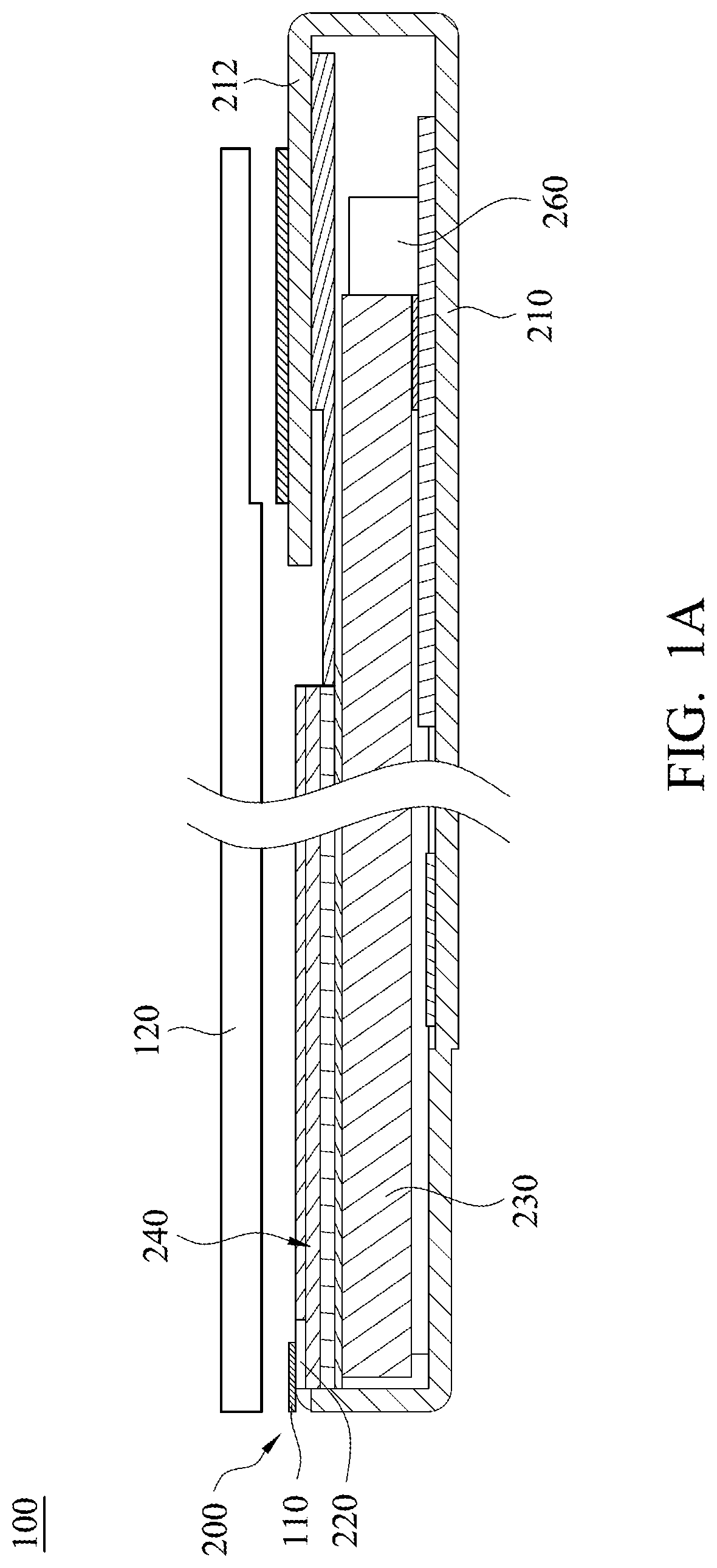
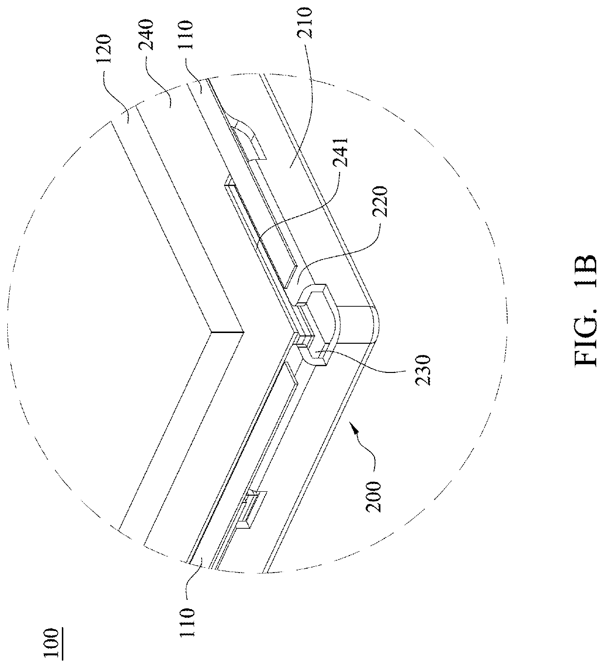
[0033]Referring to FIG. 1A and FIG. 1B, FIG. 1A and FIG. 1B are schematic partial structural diagrams showing a display device 100 in accordance with the present invention. The display device 100 of the present embodiment mainly includes a backlight module 200, plural adhesive members 110 and a display panel 120. The display panel 120 is adhered and fixed on the backlight module 200.

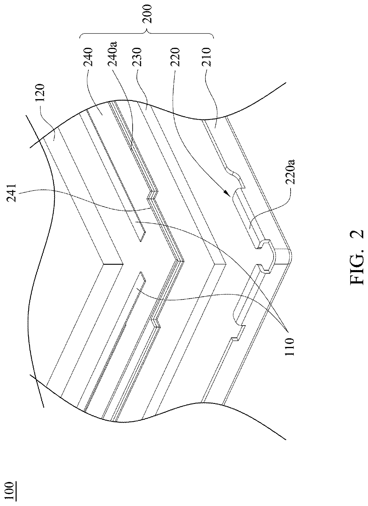
[0034]Simultaneously referring to FIG. 1A to FIG. 2, FIG. 2 is a schematic partial exploded view of the display device 100 in accordance with the first embodiment of the present invention. The backlight module 200 of present embodiment mainly includes a back plate 210, a first carrying portion 220, a light guide plate 230, at least one optical film 240 and a light source 260. The first carrying portion 220, the light guide plate 230 and the light source 260 are disposed on the back plate 210. The light source 260 is disposed adjacent to a light-incident surface of the light guide plate 230. The first car...

second embodiment

[0042]In the present invention, the back plate and the first carrying portion may have different designs. Referring to FIG. 6 and FIG. 7, FIG. 6 is a schematic partial structural diagram showing one side of a backlight module 300 away from a light-incident side in accordance with the present invention, and FIG. 7 is a schematic cross-sectional view taken along a line B-B in FIG. 6. The structure of the backlight module 300 of the present embodiment is similar to that of the aforementioned backlight module 200, and the main difference therebetween is that a back plate 310, a first carrying portion 320 and an optical film 340 of the backlight module 300 have different designs.

[0043]Referring to FIG. 6 and FIG. 7 again, a sidewall 311 of the back plate 310 has a recessed portion 311a, and the first carrying portion 320 is a spacer which is disposed in the recessed portion 311a. As shown in FIG. 7, when the first carrying portion 320 is disposed on the sidewall 311 of the back plate 310...


PUM

PropertyMeasurementUnit
widthaaaaaaaaaa
areaaaaaaaaaaa
width W1aaaaaaaaaa

Abstract

A backlight module is provided. The backlight module includes a back plate, at least one first carrying portion, a light guide plate, at least one optical film and a light source. The back plate has a sidewall. The first carrying portion is disposed on the back plate. The light guide plate is disposed on the back plate. The optical film is disposed above the light guide plate, in which the optical film has a notch which is corresponding to the first carrying portion. The light source is disposed on the back plate, in which the light source is disposed adjacent to a light-incident surface of the light guide plate.

Description

RELATED APPLICATIONS[0001]This application is a continuation application of International Application No. PCT / CN2017 / 082834 filed May 3, 2017 which is incorporated herein by reference.BACKGROUNDField of Invention[0002]The present invention relates to a light source module. More particularly, the present invention relates to a backlight module and its applications on a display device.Description of Related Art[0003]A conventional display device mainly includes a backlight module, a mold frame and a display panel. The display panel is held on the backlight module and is supported by the mold frame. The backlight module mainly includes a back plate, a light guide plate, at least one optical film and a light source, in which the light guide plate, the optical film and the light source are disposed in the back plate.[0004]Generally, the back plate has a sidewall which surrounds four its side edges, and the mold frame is fixed between the sidewall of the back plate and the light guide pla...

Claims


Application Information

Patent Timeline
Patent Type & Authority Patents(United States)
IPC IPC(8): F21V8/00
CPCG02B6/0091G02B6/0088G02B6/005G02B6/009
Inventor CHANG, CHUNG-CHENGHOU, PEI-FEN
Owner RADIANT OPTO ELECTRONICS SUZHOU
Learn More