Single point detection type microfluidic isoelectric focusing assay and chips using the same
a technology of isoelectric focusing and microfluidics, applied in the field of isoelectric focusing, can solve the problems of complex assay procedures, and achieve the effect of improving the protein assay system and reducing the size of detection equipmen
- Summary
- Abstract
- Description
- Claims
- Application Information
AI Technical Summary
Benefits of technology
Problems solved by technology
Method used
Image
Examples
example 1
[0054]A numerical simulation about a microfluidic chip isoelectric focusing based on a contactless electrical conductivity measurement was performed by using a software of Simul 5. A 10 mm microfluidic channel, 0.625 mM carrier ampholyte (CA) within a range of pH 3 to 10, a 10 μM green fluorescent protein (GFP), a 70 mM H3PO4 anode solution, a 50 mM NaOH cathode solution, and a 200 V separation voltage were used as an simulation input. In addition, conductivity and concentration data were collected and analyzed as a function of time and position. The numerical simulation results are shown in FIG. 7. FIG. 7A shows an estimation result through a simulation of a protein concentration depending on a position of a microfluidic channel. Referring to FIG. 7A, two boundaries of protein move from both ends of the microfluidic channel toward a focusing point (an isoelectric point) (a dashed arrow). One hundred seconds later after the isoelectric focusing, two protein boundaries were united at...
example 2
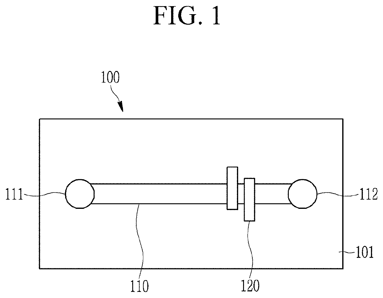
[0056]A cyclic olefin copolymer microfluidic chip having a 140 μm cover slip wherein a pair of electrodes is attached and a 18 mm straight microfluidic channel was used to analyze a protein through a microfluidic chip isoelectric focusing based on a contactless electrical conductivity measurement. The pair of electrodes has an electrode gap of 0.7 mm between themselves.
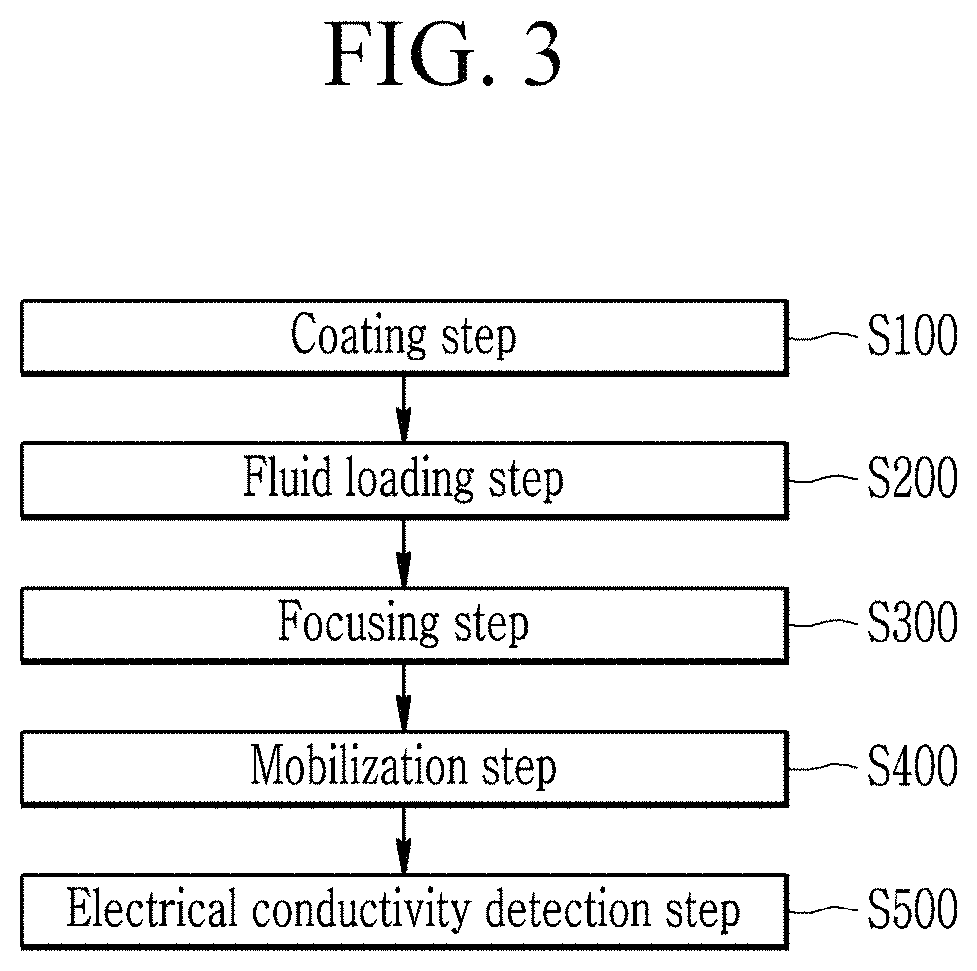
[0057]After cleaning the microfluidic chip, the internal surface of the microfluidic channel was coated with a 4% hydroxy ethyl cellulose (HEC). The HEC coating is to prevent non-specific attachment of a protein on the internal surface of the microfluidic channel and to minimize an electroosmotic flow.
[0058]A 25 μM green fluorescent protein (GFP) as a sample, a 2% carrier ampholyte (CA), and a 4% w / v HEC were loaded into the microfluidic channel. The loaded HEC functions as a dynamic coating and a separation matrix. In addition, 50 mM sodium hydroxide (NaOH) including 2% w / v HEC was added to the anode portion in the m...
PUM
| Property | Measurement | Unit |
|---|---|---|
| width | aaaaa | aaaaa |
| angle | aaaaa | aaaaa |
| diameter | aaaaa | aaaaa |
Abstract
Description
Claims
Application Information
 - R&D
- Intellectual Property
- Life Sciences
- Materials
- Tech Scout
- Unparalleled Data Quality
- Higher Quality Content
- 60% Fewer Hallucinations
Browse by: Latest US Patents, China's latest patents, Technical Efficacy Thesaurus, Application Domain, Technology Topic, Popular Technical Reports.
© 2025 PatSnap. All rights reserved.Legal|Privacy policy|Modern Slavery Act Transparency Statement|Sitemap|About US| Contact US: help@patsnap.com


