
Illumination and observation system for an ophthalmic microscope, ophthalmic microscope comprising such a system, and microscopying method

a technology of illumination and observation system and microscope, which is applied in the field of illumination and observation system of microscope, can solve the problems of difficult operation of illumination and observation system and the presence of improvement space, high manufacturing cost, etc., and achieves the effects of superior observation properties, easy operation, and inexpensive design

Active Publication Date: 2020-01-28
LEICA INSTR SINGAPORE PTE
View PDF14 Cites 0 Cited by
  • Summary
  • Abstract
  • Description
  • Claims
  • Application Information

AI Technical Summary

Benefits of technology

[0007]It is therefore the object of the invention to provide an illumination observation system that is easy to operate, inexpensive in its design, and at the same time offers superior observation properties.
[0010]Further, by coupling the main illumination to the coaxial illumination, several advantages may be realized. First, the operation of the illumination and observation system or the microscope is facilitated, as the main illumination is automatically adapted to any change of the coaxial illumination. If the coaxial illumination is adapted to produce a stronger red reflex, the main illumination also gets stronger and contrast is maintained. Second, by coupling the intensity of the main illumination to the intensity of the coaxial illumination, it is possible that an intensity of the red reflex in the second observation pupil, which in most cases is invariably generated also by the main illumination, follows the intensity of the red reflex generated by the coaxial illumination. Thus, it is possible to generate an improved stereoscopic red reflex using the main illumination in one and a coaxial illumination in another observation pupil. Finally, the inventive solution has the advantage that a stereoscopic red reflex can be maintained without the need to include another expensive coaxial illumination.
[0011]The intensity may be easily measured at the plane of observation in the observed eye, e.g. in the SI unit lux, either as the intensity reflected from the observed object or as the intensity incident on the observed eye. For the purposes of this invention, even a subjective impression of a typical observation without an objective measurement of the intensity may be sufficient.
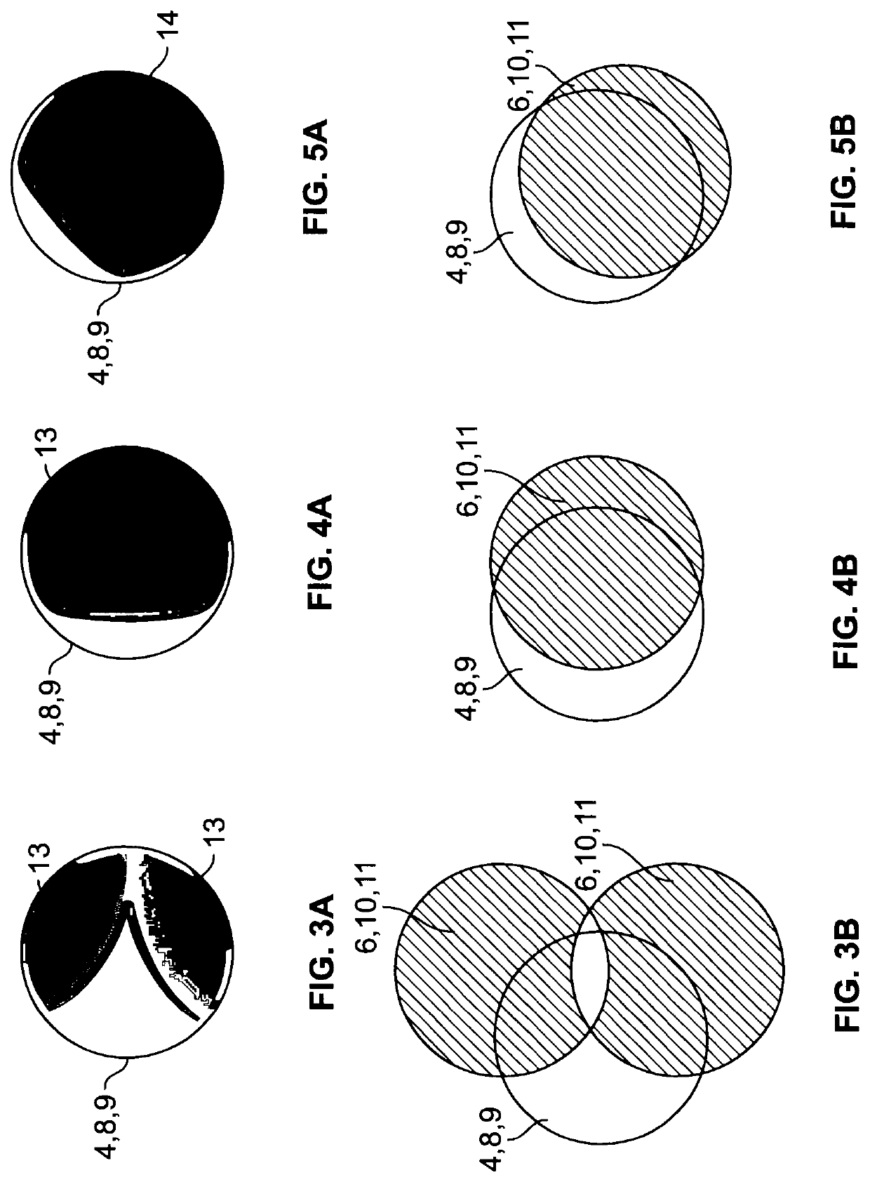
[0021]The intensity of the red reflex can be improved if the main illumination overlaps the optical axis of the second observation pupil.
[0024]The intensities of the coaxial illumination in the third and fourth observation pupil are preferably coupled to each other. For adjustment purposes, however, the illumination and observation system may be adapted to allow a decoupling of the intensities of the coaxial illumination of the third and fourth observation pupil. In the decoupled state, at least one of the intensity of the coaxial illumination in the third observation pupil and the intensity of the coaxial illumination in the fourth observation pupil may be changed independently of each other. A subsequent coupling of the intensity of the coaxial illumination of the third and fourth observation pupil may maintain the ratio of the intensities of the coaxial illumination of the third and fourth observation pupil as it has been adjusted during the decoupling. The adjustment may be realized by the manipulator subsystem and by providing a storage subsystem which is adapted to store a ratio of the intensity of the coaxial illumination in the third and fourth observation pupil, and by the control subsystem to control the coaxial illumination in the third and fourth observation system during operation to maintain this ratio.

Problems solved by technology

Operating an illumination and observation system and a microscope comprising such a system is often difficult and its manufacturing is expensive.
Further, the image quality of the known illumination and observation systems, although having made large progress in the past, still leaves room for improvement.

Method used


Image

  • Illumination and observation system for an ophthalmic microscope, ophthalmic microscope comprising such a system, and microscopying method
  • Illumination and observation system for an ophthalmic microscope, ophthalmic microscope comprising such a system, and microscopying method
  • Illumination and observation system for an ophthalmic microscope, ophthalmic microscope comprising such a system, and microscopying method

Examples


Embodiment Construction

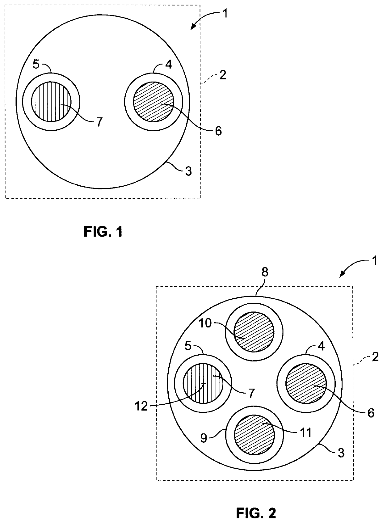
[0040]First, the design and function of an illumination and observation system 1 in a microscope 2 is explained with reference to FIG. 1. FIG. 1 shows a schematic plan view of a main objective lens 3 with a first observation pupil 4 and a second observation pupil 5. The first observation pupil 4 and the second observation pupil 5 are preferably for an assistant or a student assisting in e.g. eye surgery.

[0041]A coaxial illumination 6 is directed through the first observation pupil 4, whereas a main illumination 7 is directed through the second observation pupil 5. Preferably, there is no overlap of the main illumination with the first observation pupil 4 and / or there is no coaxial illumination in the second observation pupil 5.

[0042]The set up shown in FIG. 1 is particularly useful for microscopes 2 which are used in eye surgery, i.e. so-called ophthalmic microscopes. At the observed object, i.e. in the object plane, in such a case the eye to be operated upon, the main illumination ...


PUM


Abstract

An illumination and observation system (1), in particular for an ophthalmic microscope, comprises a first observation pupil (4) and a second observation pupil (5) for the eyes of an observer such as an assistant. Further, the system comprises a coaxial illumination (6) in the first observation pupil (4) and a main illumination (7), the coaxial illumination (6) being adapted to generate a red reflex (13) in the observed eye in operation and the main illumination having a larger field of illumination than the coaxial illumination (6, 10, 11). To facilitate usage of the system (1) and / or the microscope (2) and to create a superior stereoscopic view using the red reflex (13), a control subsystem (21, 27) is provided which is adapted to automatically adjust an intensity of the main illumination (7) depending on a change in an intensity of the coaxial illumination (6).

Description

CROSS-REFERENCE TO RELATED APPLICATIONS[0001]The present application is the U.S. national phase of International Application No. PCT / SG2016 / 000011 filed Aug. 23, 2016, which claims priority of European Application No. 15182105.5 filed Aug. 24, 2015, the entire disclosure of which is incorporated herein by reference.FIELD OF THE INVENTION[0002]The invention relates to an illumination and observation system for a microscope, in particular a microscope for performing eye surgery, wherein the system comprises a first and second observation pupil for the eyes of an observer such as an assistant, a coaxial illumination in the first observation pupil, the coaxial illumination being adapted to generate a red reflex in the observed eye in operation.[0003]The invention further relates to a microscope, in particular for eye surgery comprising such a system. Finally, the invention relates to a microscopying method by using a coaxial illumination to illuminate the object coaxially through a firs...

Claims


Application Information

Patent Timeline
Patent Type & Authority Patents(United States)
IPC IPC(8): G02B21/08G02B21/00A61F9/007G02B21/22
CPCG02B21/0012G02B21/22G02B21/082A61F9/007A61B3/132A61B3/152
Inventor KUSTER, MANFREDGUENTERT, MICHAEL
Owner LEICA INSTR SINGAPORE PTE
Learn More