Oven appliance with spill control and heat regulating features

a technology of spill control and heat regulation, which is applied in the direction of domestic stoves or ranges, heating types, lighting and heating apparatus, etc., can solve the problems of large amount of heat generated by the heating elements associated with the cooking chamber and/or the cooktop, affecting the operation of control electronics and other electronic components, and liquid spillage through the vent aperture and into the cabinet, and a large amount of liquid spillage can be significant to the electronics of such electronics

Active Publication Date: 2019-12-03
HAIER US APPLIANCE SOLUTIONS INC
View PDF9 Cites 6 Cited by
  • Summary
  • Abstract
  • Description
  • Claims
  • Application Information

AI Technical Summary

Problems solved by technology

Notably, the large amount of heat generated by the heating elements associated with the cooking chamber and / or the cooktop can be detrimental to the operation of the control electronics and other electronic components.
For example, when liquids within a utensil (e.g., pot) boil over and out of the utensil, the liquids may spill through the vent apertures and into the cabinet.
Notably, some appliances include one or more electronic components that are mounted within cabinet, and spilled fluids risk significantly damaging such electronics.

Method used


Image

  • Oven appliance with spill control and heat regulating features
  • Oven appliance with spill control and heat regulating features
  • Oven appliance with spill control and heat regulating features

Examples


Embodiment Construction

[0024]Reference now will be made in detail to embodiments of the invention, one or more examples of which are illustrated in the drawings. Each example is provided by way of explanation of the invention, not limitation of the invention. In fact, it will be apparent to those skilled in the art that various modifications and variations can be made in the present invention without departing from the scope or spirit of the invention. For instance, features illustrated or described as part of one embodiment can be used with another embodiment to yield a still further embodiment. Thus, it is intended that the present invention covers such modifications and variations as come within the scope of the appended claims and their equivalents.

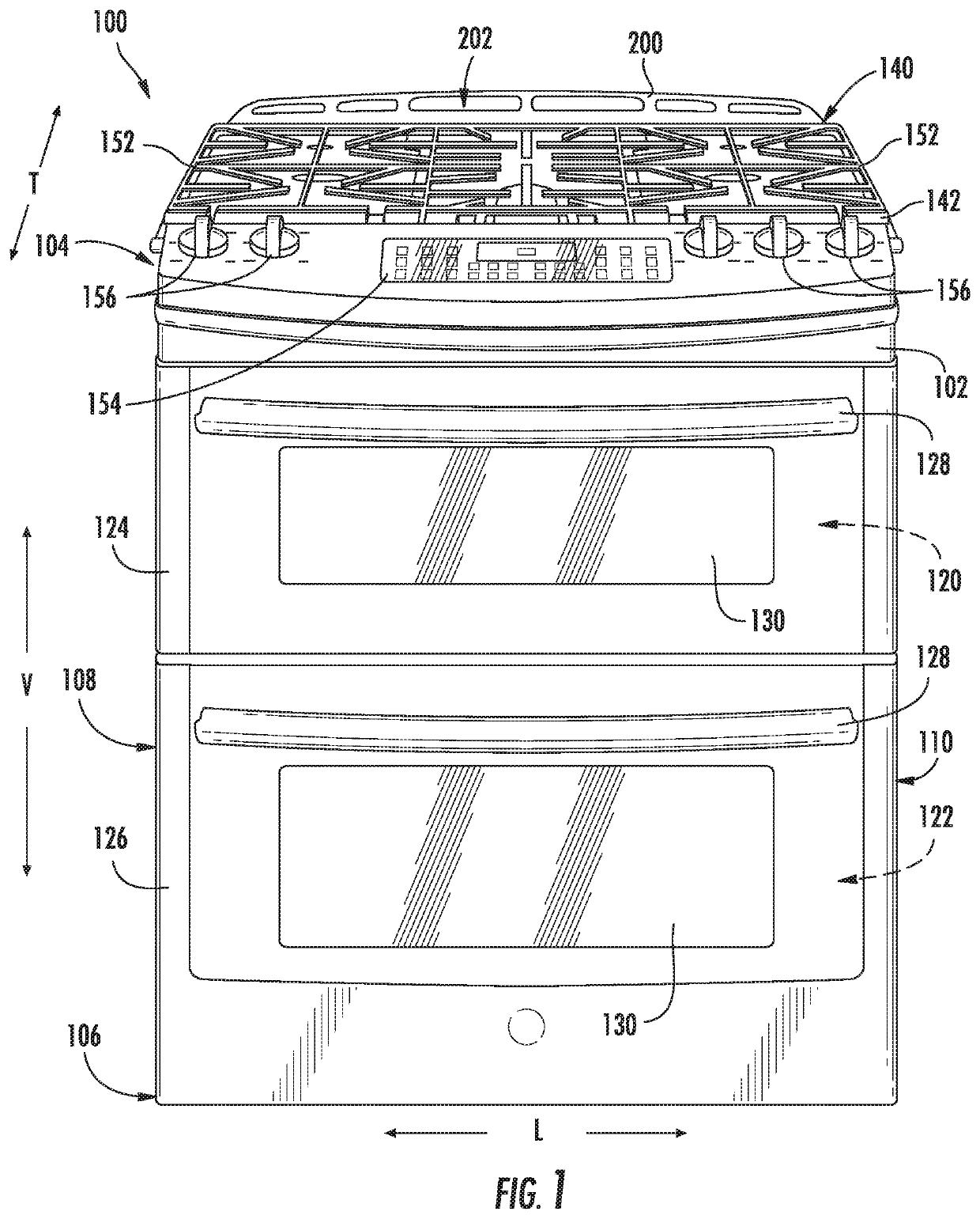
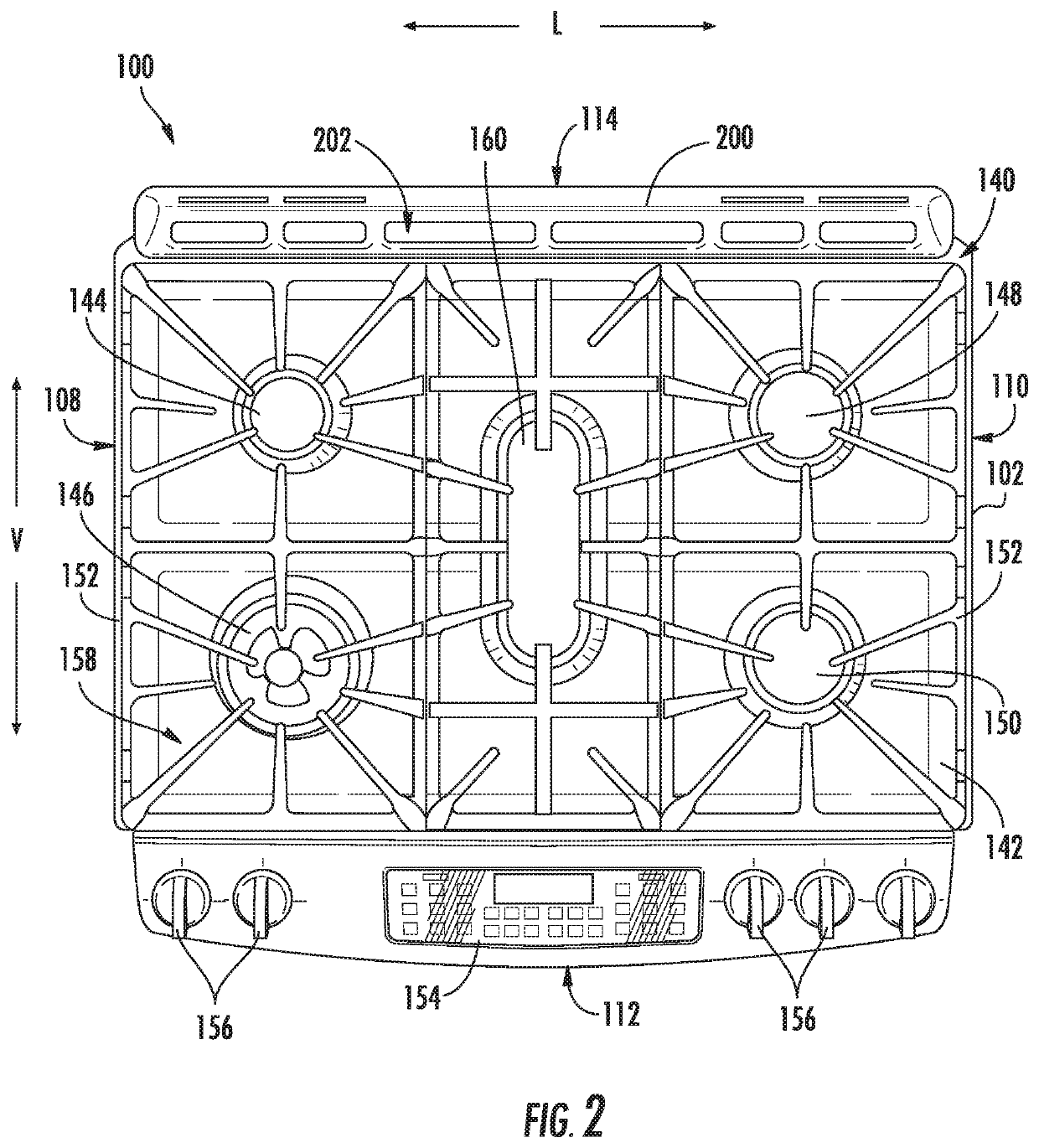
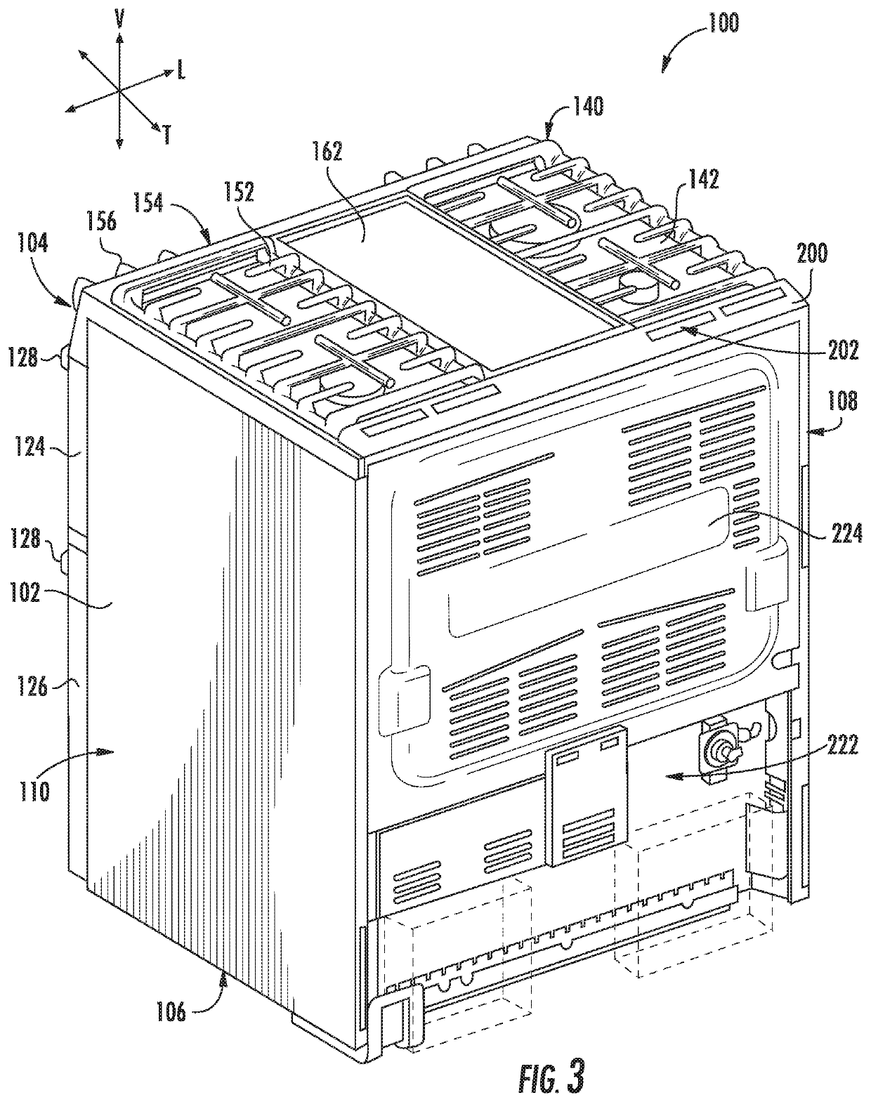
[0025]FIG. 1 provides a front, perspective view of an oven appliance 100 as may be employed with the present subject matter. FIG. 2 provides a top, plan view of oven appliance 100. Oven appliance 100 includes an insulated cabinet 102. Cabinet 102 defines an...


PUM


Abstract

An oven appliance having an oven chamber positioned within a cabinet and a top panel defining one or more vent apertures includes a false back assembly for facilitating the containment of spilled fluids and the cooling of electronic components within the cabinet. The false back assembly includes a false back spaced apart from a range back to define a spill channel. A spill deflector is positioned below the vent apertures and above the spill channel along the vertical direction such that the spill deflector is configured for collecting fluids spilled through the vent apertures and directing the spilled fluids to the spill channel where they may be safely routed around sensitive electronic components.

Description

FIELD OF THE INVENTION[0001]The present subject matter relates generally to oven appliances, and more particularly, to oven appliances with features for protecting electronic components from fluid spills and excessive heat.BACKGROUND OF THE INVENTION[0002]Conventional residential and commercial oven appliances generally include a cabinet that defines a cooking chamber for receipt of food items for cooking. Multiple heating elements are positioned within the cooking chamber to provide heat to food items located therein. The heating elements can include, for example, radiant heating elements, such as a bake heating assembly positioned at a bottom of the cooking chamber and / or a separate broiler heating assembly positioned at a top of the cooking chamber.[0003]In addition, conventional oven appliances may include a cooktop positioned on a top panel of the appliance. The cooktop may include multiple heating elements for heating utensils placed thereon, such as electric, induction, or ga...

Claims


Application Information

Patent Timeline
Patent Type & Authority Patents(United States)
IPC IPC(8): F24C15/00F24C15/32F24C15/36
CPCF24C15/007F24C15/32F24C15/36F24C15/08F24C15/12
Inventor TORRENTES, MARCELOMAYNE, JOSHUA ADAMBIERBAUM, CHARLES ANDREW
Owner HAIER US APPLIANCE SOLUTIONS INC
Why Eureka
Try Eureka