
Vehicle headlight

a headlight and vehicle technology, applied in the field of vehicle headlights, can solve the problems of increasing the size of the vehicle headlight, affecting the use of the vehicle, so as to reduce the size of the projection lens and good light distribution pattern

Active Publication Date: 2019-11-05
STANLEY ELECTRIC CO LTD
View PDF17 Cites 5 Cited by
  • Summary
  • Abstract
  • Description
  • Claims
  • Application Information

AI Technical Summary

Benefits of technology

The present invention provides a vehicle headlight that can create a good lighting pattern without being obtrusive to the driver. It achieves this by using a special light distribution pattern that maximizes the amount of light in the center and reduces the size of the projection lens. This headlight also enhances the intensity of the light when projecting it onto a virtual screen in front of the driver. Overall, this innovation improves the safety and driver experience of vehicles.

Problems solved by technology

Incidentally, when a plurality of light emitting devices are disposed to be arranged in a vehicle width direction, it is extremely difficult to dispose them parallel to each other with no gaps therebetween.
In this case, the clear cutoff line formed in the light distribution pattern may be annoying for a driver.
In this case, in order to raise the central luminous intensity of the light distribution pattern, it is simply necessary to enlarge the projection lens, but this will lead to an increase in size of the vehicle headlight.

Method used


Image

  • Vehicle headlight
  • Vehicle headlight
  • Vehicle headlight

Examples


Embodiment Construction

[0031]Hereinafter, an embodiment of the present invention will be described with reference to the accompanying drawings.

[0032]In the drawings used in the following description, in order to make respective components easy to see, there are instances where the dimensional sizes are made different depending on the constituent elements, and the dimensional proportions of respective components may not necessarily be the same as actual ones. In addition, materials, dimensions, and so on, exemplified in the following descriptions are merely examples, and the present invention is not limited thereto and may be made with appropriate modifications without departing from the scope of the present invention.

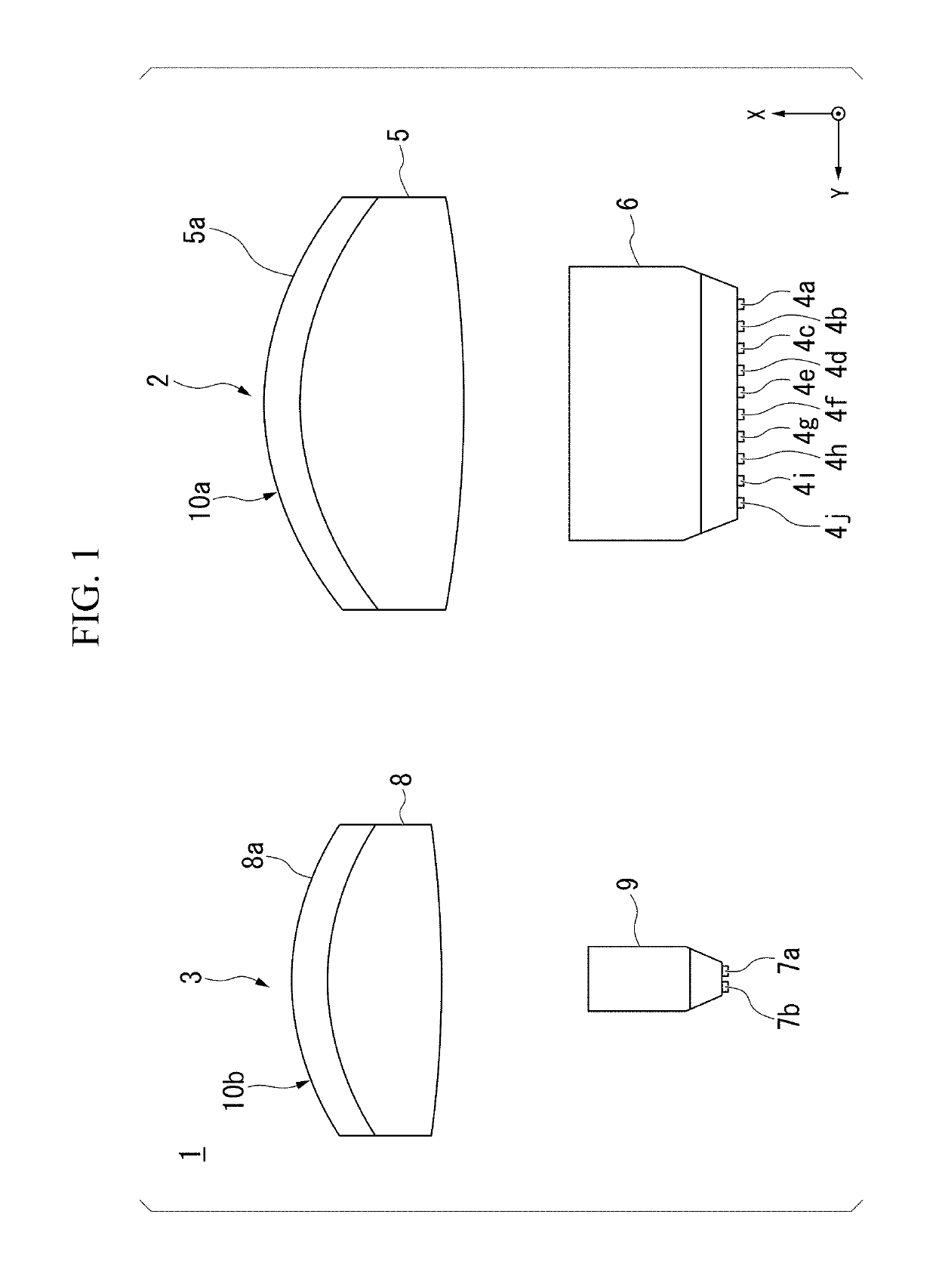
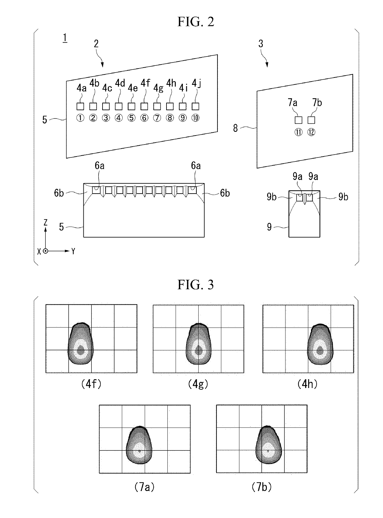
[0033]For example, a vehicle headlight 1 shown in FIG. 1 to FIG. 4 will be described as an embodiment of the present invention.

[0034]Further, FIG. 1 is a plan view showing a schematic configuration of the vehicle headlight 1. FIG. 2 is an exploded view of configurations of a first light distr...


PUM


Abstract

A vehicle headlight includes a first light distribution variable lighting unit and a second light distribution variable lighting unit each having a plurality of light emitting devices and a projection lens that projects light emitted from the plurality of light emitting devices and that are configured to variably control a light distribution pattern of light emitted from the projection lens while switching lighting of the plurality of light emitting devices, wherein the first light distribution variable lighting unit radiates light having a first light distribution pattern toward a side in front of the projection lens with respect to a predetermined radiation range, and the second light distribution variable lighting unit radiates light having a second light distribution pattern toward the side in front of the projection lens with respect to at least a vicinity of a reference center of the radiation range.

Description

CROSS-REFERENCE TO RELATED APPLICATION[0001]Priority is claimed on Japanese Patent Application No. 2017-225182, filed Nov. 22, 2017, the content of which is incorporated herein by reference.BACKGROUND OF THE INVENTIONField of the Invention[0002]The present invention relates to a vehicle headlight.Description of Related Art[0003]In the related art, for a vehicle headlight mounted on a vehicle, there is a configuration including a plurality of light emitting devices disposed to be arranged in a vehicle width direction, and a projection lens configured to project light emitted from the plurality of light emitting devices in an advancing direction of the vehicle (for example, see Japanese Unexamined Patent Application, First Publication No. 2004-311101).[0004]With regard to this, development of a variable light distribution headlamp (an adaptive driving beam (ADB)) configured to variably control a light distribution pattern of light projected by a projection lens while switching the lig...

Claims


Application Information

Patent Timeline
Patent Type & Authority Patents(United States)
IPC IPC(8): F21S41/663F21S41/151F21S41/30F21S41/275F21S41/143F21S41/26F21S41/32F21S41/36
CPCF21S41/151F21S41/26F21S41/36F21S41/143F21S41/663F21S41/323F21S41/30F21S41/275F21S41/321F21W2102/16F21S41/153
Inventor NAKAZATO, YOSHIAKI
Owner STANLEY ELECTRIC CO LTD
Learn More