
Method for displaying a vehicle environment of a vehicle

a vehicle environment and vehicle technology, applied in the field of vehicle environment display, can solve the problems of unintentional differences and unintentional differences, and achieve the effect of preventing collisions and minimizing unintentional differences

Active Publication Date: 2019-05-14
ROBERT BOSCH GMBH
View PDF13 Cites 3 Cited by
  • Summary
  • Abstract
  • Description
  • Claims
  • Application Information

AI Technical Summary

Benefits of technology

The patent describes a method and device for creating a virtual space that includes a virtual model of a vehicle and a depth map that describes the distance between the virtual model and the virtual camera. The virtual model is placed in the virtual space and the depth map is set up to make it appear as if the virtual model is in the same distance range as the virtual camera. This creates a realistic and immersive virtual space that allows the user to interact with the virtual model of the vehicle. The virtual model can also be oriented to a specific point of interest, such as a point where the vehicle approaches an object, to alert the user and prevent collisions. The device that implements this method is also described.

Problems solved by technology

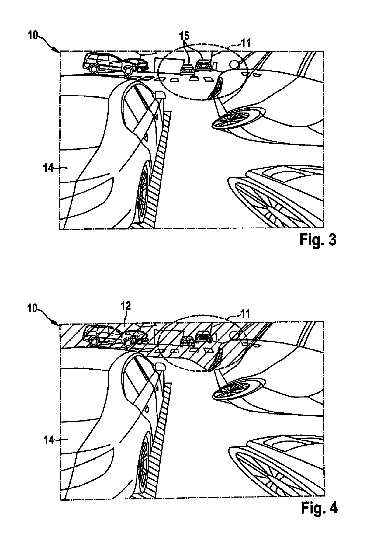
Also, unintentional differences between the image from the virtual camera and the vehicle environment that the virtual camera images and that appear in the particular regions of the geometrical projection surface are blurred and therefore hidden, in particular.
Such unintentional differences sometimes result from the fact that the geometrical projection surface in the virtual space does not precisely reproduce the vehicle environment in its form.

Method used


Image

  • Method for displaying a vehicle environment of a vehicle
  • Method for displaying a vehicle environment of a vehicle
  • Method for displaying a vehicle environment of a vehicle

Examples


second specific embodiment

[0052]the present invention corresponds to the first specific embodiment of the present invention. However, the method according to the present invention additionally encompasses a further step, in which an orientation of the virtual camera to a particular point of interest in the virtual space takes place. The particular point of interest is a point at which the vehicle is approaching an object.

[0053]For this purpose, it is ascertained with the aid of the distance sensor system of vehicle 1 whether vehicle 1 is approaching an object. The point of interest here is a center of the region of the vehicle environment in which an approach of the object to vehicle 1 takes place. The position of the virtual camera is selected in such a way that it lies directly above point of interest 16 in the virtual space, and an orientation of the virtual camera is selected such that the virtual camera looks down on point of interest 16 from the bird's eye perspective.

[0054]FIG. 5 shows an image 10 fro...


PUM


Abstract

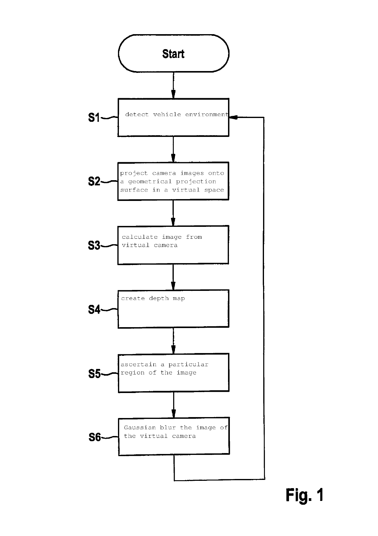
A method for displaying a vehicle environment of a vehicle, including a detection of the vehicle environment in camera images with the aid of a plurality of cameras; projecting the camera images onto a geometrical projection surface in a virtual space, setting up a depth map for a visual range of a virtual camera that describes a distance of a plurality of points of the geometrical projection surface from the virtual camera in the virtual space; calculating an image from the virtual camera that images the geometrical projection surface in the virtual space; ascertaining, based on the depth map, a particular region of the image from the virtual camera in which the geometrical projection surface lies in a certain distance range in relation to the virtual camera; and Gaussian blurring of the image from the virtual camera in the region in which the particular region is imaged.

Description

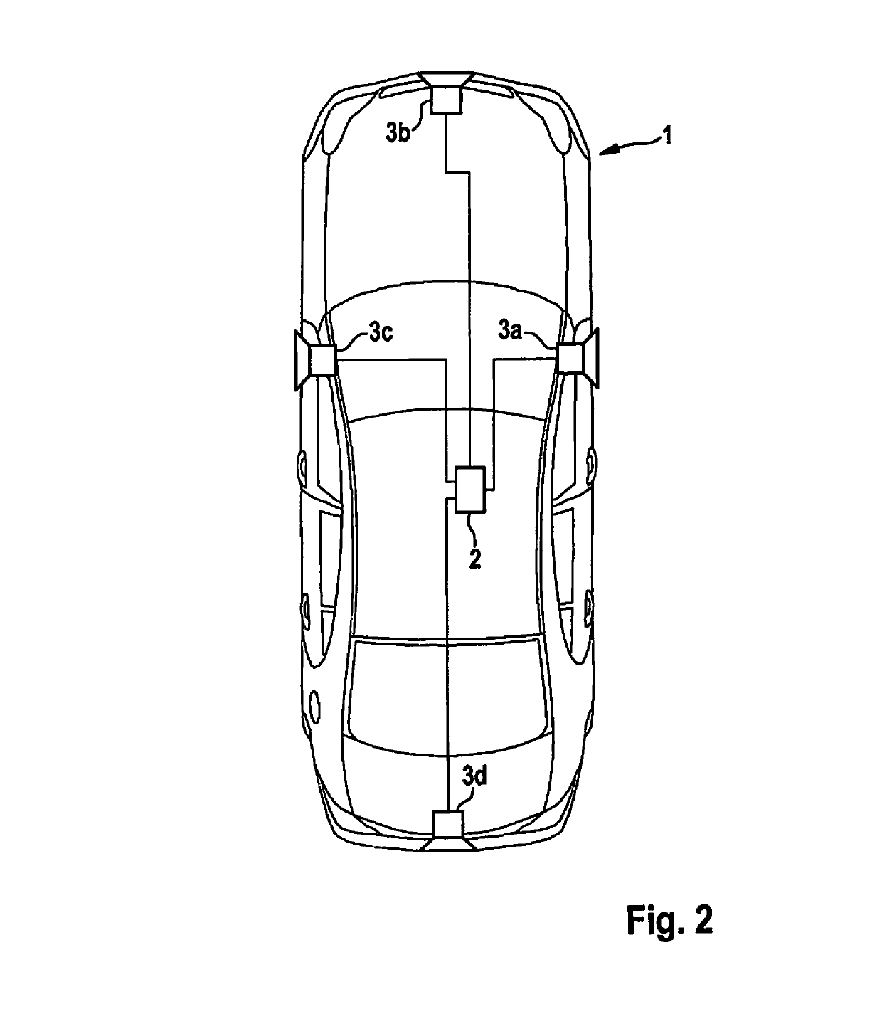
FIELD[0001]The present invention relates to a method for displaying a vehicle environment of a vehicle.BACKGROUND INFORMATION[0002]Driver-assistance systems aim to assist a driver in controlling a vehicle. Such an assistance of the driver may be provided by the following functions:[0003]Displaying an environment in close range of the vehicle in order to avoid collisions with obstacles that are not located in the driver's direct field of vision;[0004]Assuming some of the tasks of the driver in order to enhance the driving comfort for the driver;[0005]Monitoring activities of the driver, and intervening in dangerous situations; and / or[0006]Automated driving without the driver necessarily having to be present.[0007]In particular, the present invention relates to a method for displaying a vehicle environment with the aid of a composite view as it takes place especially in what is known as a surround view system. In such surround view systems, multiple cameras are typically mounted on a ...

Claims


Application Information

Patent Timeline
Patent Type & Authority Patents(United States)
IPC IPC(8): B60R1/00G06T15/50G06T5/20G06T15/20H04N5/00G06T5/00G06T3/40H04N5/232H04N5/247H04N23/90
CPCG06T3/4038B60R1/00G06T5/002G06T5/20G06T15/205G06T15/503H04N5/247B60R2300/105B60R2300/30B60R2300/8093H04N5/23238B60R1/27G06T7/50G06T2207/10028H04N23/90H04N23/698G06T5/70
Inventor ESPARZA GARCIA, JOSE DOMINGOCANO, RAPHAEL
Owner ROBERT BOSCH GMBH
Learn More