
Medical robotic system providing an auxiliary view of articulatable instruments extending out of a distal end of an entry guide

a robotic system and auxiliary view technology, applied in the field of medical robotic systems, can solve the problems of affecting the positioning of patients, adversely affecting the performance of medical procedures, etc., and it is more difficult for operators to avoid collisions between linkages, so as to improve the operator's understanding of the configuration

Active Publication Date: 2019-04-16
INTUITIVE SURGICAL OPERATIONS INC
View PDF568 Cites 198 Cited by
  • Summary
  • Abstract
  • Description
  • Claims
  • Application Information

AI Technical Summary

Benefits of technology

[0011]Another object of one or more aspects of the present invention is a method implemented in such a medical robotic system that improves an operator's understanding of the configuration of the linkages of the articulatable instruments that are outside of the field of view of a camera.

Problems solved by technology

Since the entry guide generally has a relatively small diameter in order to fit through a minimally invasive incision or a natural body orifice, a number of problems may arise while teleoperating the surgical tools to perform the medical procedure and the camera to view it.
For example, because the camera is bundled with the surgical tools, it is limited in its positioning relative to the surgical tools and consequently, its view of the surgical tools.
As a consequence, the controllable linkages of the surgical tools may inadvertently collide with each other (or with a link of the camera) during the performance of a medical procedure and as a result, cause harm to the patient or otherwise adversely impact the performance of the medical procedure.
Also, since the articulatable camera is generally incapable of viewing its own controllable linkage, operator movement of the camera is especially a concern where collisions with the surgical tool links are to be avoided.
Further, when intuitive control is provided to assist the operator in teleoperatively moving the surgical tools and camera, the motions of the linkages required to produce such intuitive motions of the tips of the tools and camera may not be obvious or intuitive to the operator, thus making it even more difficult for the operator to avoid collisions between linkages that are outside the field of view of the camera.

Method used


Image

  • Medical robotic system providing an auxiliary view of articulatable instruments extending out of a distal end of an entry guide
  • Medical robotic system providing an auxiliary view of articulatable instruments extending out of a distal end of an entry guide
  • Medical robotic system providing an auxiliary view of articulatable instruments extending out of a distal end of an entry guide

Examples


Embodiment Construction

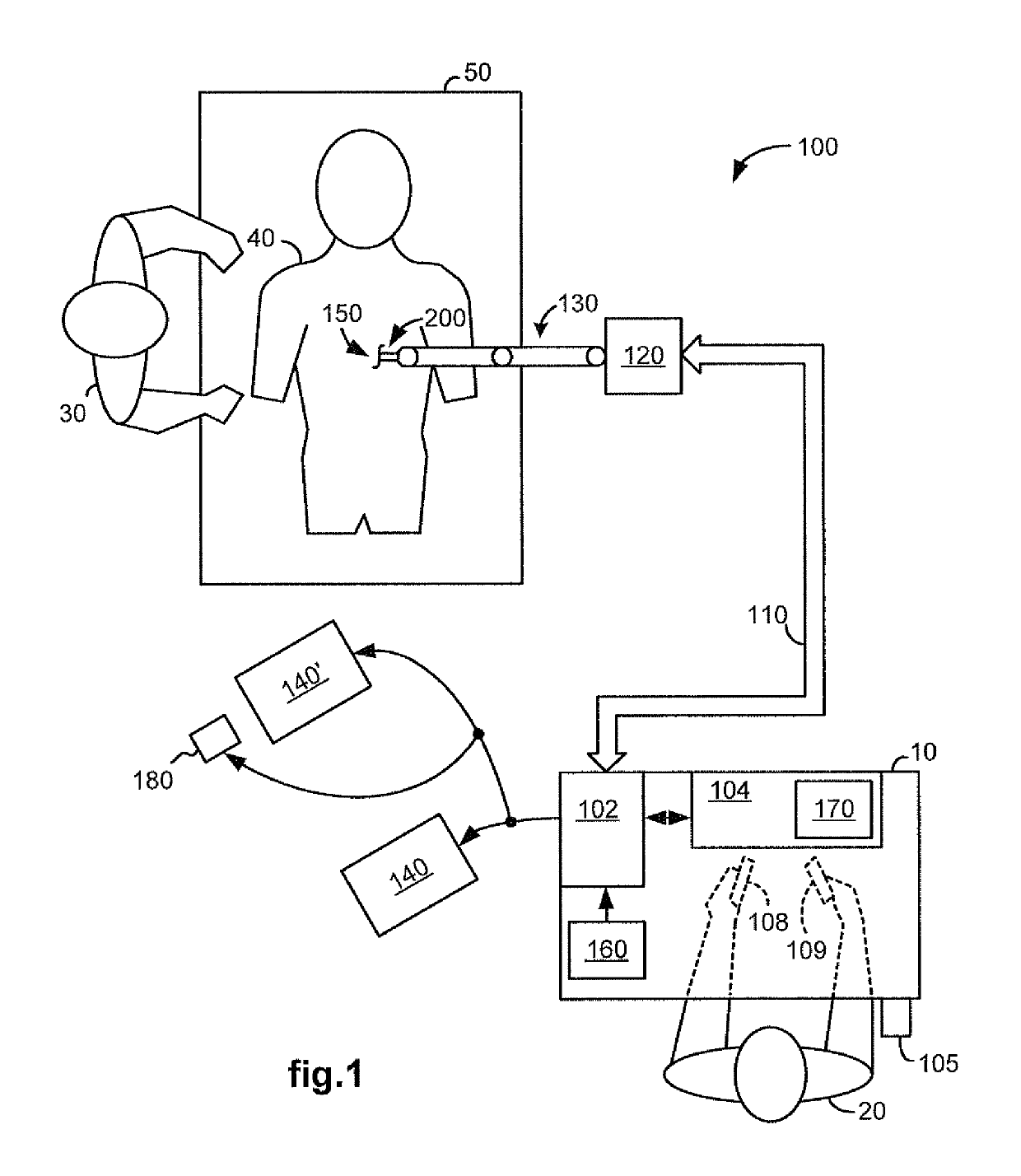
[0031]FIG. 1 illustrates, as an example, a top view of an operating room in which a medical robotic system 100 is being utilized by a Surgeon 20 for performing a medical procedure on a Patient 40 who is lying face up on an operating table 50. One or more Assistants 30 may be positioned near the Patient 40 to assist in the procedure while the Surgeon 20 performs the procedure teleoperatively by manipulating input devices 108, 109 on a surgeon console 10.

[0032]In the present example, an entry guide (EG) 200 is inserted through a single entry aperture 150 into the Patient 40. Although the entry aperture 150 is a minimally invasive incision in the present example, in the performance of other medical procedures, it may instead be a natural body orifice. The entry guide 200 is held and manipulated by a robotic arm assembly 130 that is mounted to a support 120.

[0033]As with other parts of the medical robotic system 100, the illustration of the robotic arm assembly 130 is simplified in FIG....


PUM


Abstract

A medical robotic system includes an entry guide with surgical tools and a camera extending out of its distal end. To supplement the view provided by an image captured by the camera, an auxiliary view including articulatable arms of the surgical tools and / or camera is generated from sensed or otherwise determined information about their positions and orientations and displayed on a display screen from the perspective of a specified viewing point.

Description

FIELD OF THE INVENTION[0001]The present invention generally relates to medical robotic systems and in particular, to a medical robotic system providing an auxiliary view of articulatable instruments extending out of a distal end of an entry guide.BACKGROUND OF THE INVENTION[0002]Medical robotic systems such as teleoperative systems used in performing minimally invasive surgical procedures offer many benefits over traditional open surgery techniques, including less pain, shorter hospital stays, quicker return to normal activities, minimal scarring, reduced recovery time, and less injury to tissue. Consequently, demand for such medical robotic systems is strong and growing.[0003]One example of such a medical robotic system is the da Vinci® Surgical System from Intuitive Surgical, Inc., of Sunnyvale, Calif., which is a minimally invasive robotic surgical system. The da Vinci® Surgical System has a number of robotic arms that move attached medical devices, such as an image capturing dev...

Claims


Application Information

Patent Timeline
Patent Type & Authority Patents(United States)
IPC IPC(8): A61B1/00A61B90/00A61B34/30A61B34/00A61B34/37A61B34/10A61B17/00A61B34/20
CPCA61B90/36A61B34/30A61B34/37A61B34/74A61B34/20A61B2090/365A61B90/361A61B2017/00119A61B2034/102A61B2034/305A61B2090/364A61B90/03A61B1/04B25J19/04
Inventor MUSTUFA, TABISHDIOLAITI, NICOLALARKIN, DAVID Q.
Owner INTUITIVE SURGICAL OPERATIONS INC
Learn More