Electric machine having asymmetric magnetic pole shape for torque ripple reduction

a technology of asymmetric magnetic poles and torque ripple reduction, which is applied in the direction of dynamo-electric machines, magnetic circuit rotating parts, magnetic circuit shape/form/construction, etc., can solve the problems of difficult control of position, undesirable vibration and noise, etc., and achieve the effect of reducing the torque rippl

Active Publication Date: 2019-04-09
KOREA ELECTROTECH RES INST
View PDF37 Cites 1 Cited by
  • Summary
  • Abstract
  • Description
  • Claims
  • Application Information

AI Technical Summary

Benefits of technology

[0004]Accordingly, the present invention has been made keeping in mind the above problems occurring in the related art, and an object of the present invention is to provide an electric machine, in which magnetic poles having an asymmetric shape and an asymmetric arrangement and various configurations thereof are applied to a stator and a mover or rotor, thus being capable of reducing the torque ripple of the electric machine.
[0025]As is apparent from the above description, the electric machine according to the present invention is advantageous in that the asymmetric shape and the asymmetric arrangement of the magnetic poles are applied to the stator and the mover or rotor, namely, the shape in which the asymmetric permanent magnet or the permanent magnet is embedded in the core, the shape of the consequent pole created by substituting the core for the N- or S-pole, the magnetic-flux concentrating structure, or the Halbach array is implemented and applied, thus effectively reducing a torque ripple.

Problems solved by technology

A general electric machine, such as a conventional permanent magnet linear synchronous motor according to the cited document, is problematic in that many permanent magnets are used at the stator, the mover, the rotor or the like, as shown in FIG. 1, so that it is difficult to control a position due to a torque (thrust) ripple, and vibrations and noise are undesirably generated.

Method used


Image

  • Electric machine having asymmetric magnetic pole shape for torque ripple reduction
  • Electric machine having asymmetric magnetic pole shape for torque ripple reduction
  • Electric machine having asymmetric magnetic pole shape for torque ripple reduction

Examples


Embodiment Construction

[0043]The above and other objects and features of the invention will be described more fully hereinafter with reference to the accompanying drawings, in which example embodiments of the inventions are shown.

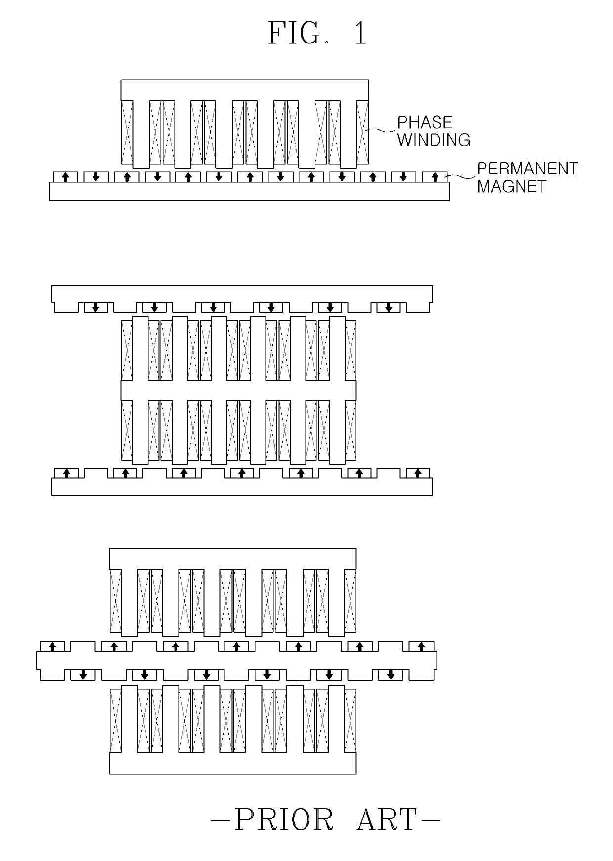
[0044]The electric machine mentioned in the present invention means various application devices including a motor that requires a rotary motion or a linear motion, such as a direct driving field, a power generator, a compressor, a finishing machine, an electric car, or an industrial electric machine. In these various devices, the electric machine of the present invention may include a stator and a mover that is opposite to the stator and performs a linear or curvilinear motion. Alternatively, the electric machine may include a stator and a rotor that is opposite to the stator and performs a rotary motion. In this context, a relative motion between the stator and the mover or between the stator and the rotor may be performed by an electromagnetic force generated between a phase wi...


PUM


Abstract

There is provided an electric machine, which is configured such that magnetic poles provided on a stator and a mover or rotor of the electric machine have an asymmetric shape, thus being capable of reducing a torque ripple.

Description

BACKGROUND OF THE INVENTION1. Field of the Invention[0001]The present invention relates, in general, to an electric machine, such as a motor, and, more particularly, to an electric machine, which is configured such that magnetic poles provided on a stator and a mover or rotor of the electric machine have an asymmetric shape, thus being capable of reducing a torque ripple.2. Description of the Related Art[0002]As a patent document related to the present invention, Korean Patent Application Publication No. 10-2011-0001465 (published on Jan. 6, 2011) has been proposed.[0003]A general electric machine, such as a conventional permanent magnet linear synchronous motor according to the cited document, is problematic in that many permanent magnets are used at the stator, the mover, the rotor or the like, as shown in FIG. 1, so that it is difficult to control a position due to a torque (thrust) ripple, and vibrations and noise are undesirably generated.SUMMARY OF THE INVENTION[0004]According...

Claims


Application Information

Patent Timeline
Patent Type & Authority Patents(United States)
IPC IPC(8): H02K41/03H02K1/24H02K29/03H02K1/27
CPCH02K1/24H02K1/276H02K41/031H02K1/2746H02K29/03H02K1/278H02K1/2783H02K1/06H02K1/14H02K1/27H02K41/02
Inventor CHUNG, SHI UKWOO, BYUNG CHULLEE, JI YOUNGCHUN, YON DOHONG, DO KWAN
Owner KOREA ELECTROTECH RES INST
Why Eureka
Try Eureka