Trajectory adjustment structure of gun

a technology of trajectory adjustment and gun barrel, which is applied in the direction of spring guns, compressed gas guns, white arms/cold weapons, etc., can solve the problems of sacrificing one hand for the operation of adjustment, the inability to correct the and the difficulty in controlling the precision of the trajectory adjustment. , to achieve the effect of improving the stability of adjustment operation, improving the correction of trajectory, and easy replacement of the gun barrel

Active Publication Date: 2019-03-05
GUAY GUAY TRADING CO LTD
View PDF6 Cites 1 Cited by
  • Summary
  • Abstract
  • Description
  • Claims
  • Application Information

AI Technical Summary

Benefits of technology

[0005]The primary objective of the present invention is to provide an adjustment assembly that allows for precise adjustment through an arrangement of thread sections in order to achieve the purpose of fine adjustment of a hop-up force to thereby help improve correction of trajectory and also allows a trajectory adjustment mechanism to be mounted inside a gun barrel to allow for easy replacement of the gun barrel, and also to help improve operation stability of adjustment through direct operation of the adjustment assembly that is mounted at a front end of the gun barrel.
[0006]To achieve the above objective, the present invention is mountable in a gun barrel and has a main structure that comprises: an adjustment assembly arranged at a front end of the gun barrel. The gun barrel is provided therein with a connection tube in abutting engagement with the adjustment assembly and is movable as being driven by the adjustment assembly. The adjustment assembly is formed thereon with a plurality of thread sections that are in threading engagement with the gun barrel for a fine adjustment operation of the adjustment assembly. The connection tube is provided, on one end thereof that is distant from the adjustment assembly, with at least one transmission sleeve. The transmission sleeve is provided, on one side thereof, with a press-down member, which is in abutting engagement with the transmission sleeve for being pressed inwardly of the gun barrel. When a user attempts to adjust a trajectory by using the present invention, it only needs to simply rotate the adjustment assembly provided at the front end of the gun barrel so that wobbling of the gun during the operation of adjustment could be avoided. In addition, due to an effect provided by the thread sections, a depth of the connection tube could be continuously changed as being slowly pushed such that the transmission sleeve arranged at an opposite end of the connection tube could slowly change a position of abutting engagement thereof with the press-down member to cause the press-down member to gradually press inwardly of the gun barrel to set an upper side of an inside wall of the gun barrel in a concave configuration that could provide a frictional force to a top of a BB bullet moving through the gun barrel so as to apply a hop-up or lifting force to the BB bullet, imposing a force of moving upward after being shot. Through a fine adjustment operation conducted with the adjustment assembly, a trajectory of the BB bullet could be changed in a precise manner. Due to the present invention being directly coupled in the gun barrel, replacement of the gun barrel is made convenient.
[0007]A such, in view of the conventional measure for adjustment of a trajectory of a toy gun being rough and inaccurate so that it is hard to provide precise control of the trajectory, the adjustment operation may readily cause wobbling of the gun, and the adjustment structure is such that the replacement of the gun barrel is difficult, the present invention provides a solution that overcomes such problems and achieves an advantage of improving utilization thereof.

Problems solved by technology

It may occasionally occur that the replacement of gun barrel cannot be correctly carried out due to difference of design.
Further, the conventional hop-up adjustment mechanism involves an adjustment means that is rough and adjustment is often conducted with a pin or a rotary wheel such that each step of adjustment involves a significant change of the hop-up force, making it hard to control the precision of adjustment of a trajectory.
However, the operation of adjustment would need sacrificing one hand for not holding the gun by moving the hand to the rear end of the gun barrel where the hop-up adjustment mechanism is located to conduct the adjustment.
This would cause wobbling of the gun, and thus losing the significance of fine adjustment for trajectory.

Method used


Image

  • Trajectory adjustment structure of gun
  • Trajectory adjustment structure of gun
  • Trajectory adjustment structure of gun

Examples


Embodiment Construction

[0020]The following descriptions are exemplary embodiments only, and are not intended to limit the scope, applicability or configuration of the invention in any way. Rather, the following description provides a convenient illustration for implementing exemplary embodiments of the invention. Various changes to the described embodiments may be made in the function and arrangement of the elements described without departing from the scope of the invention as set forth in the appended claims.

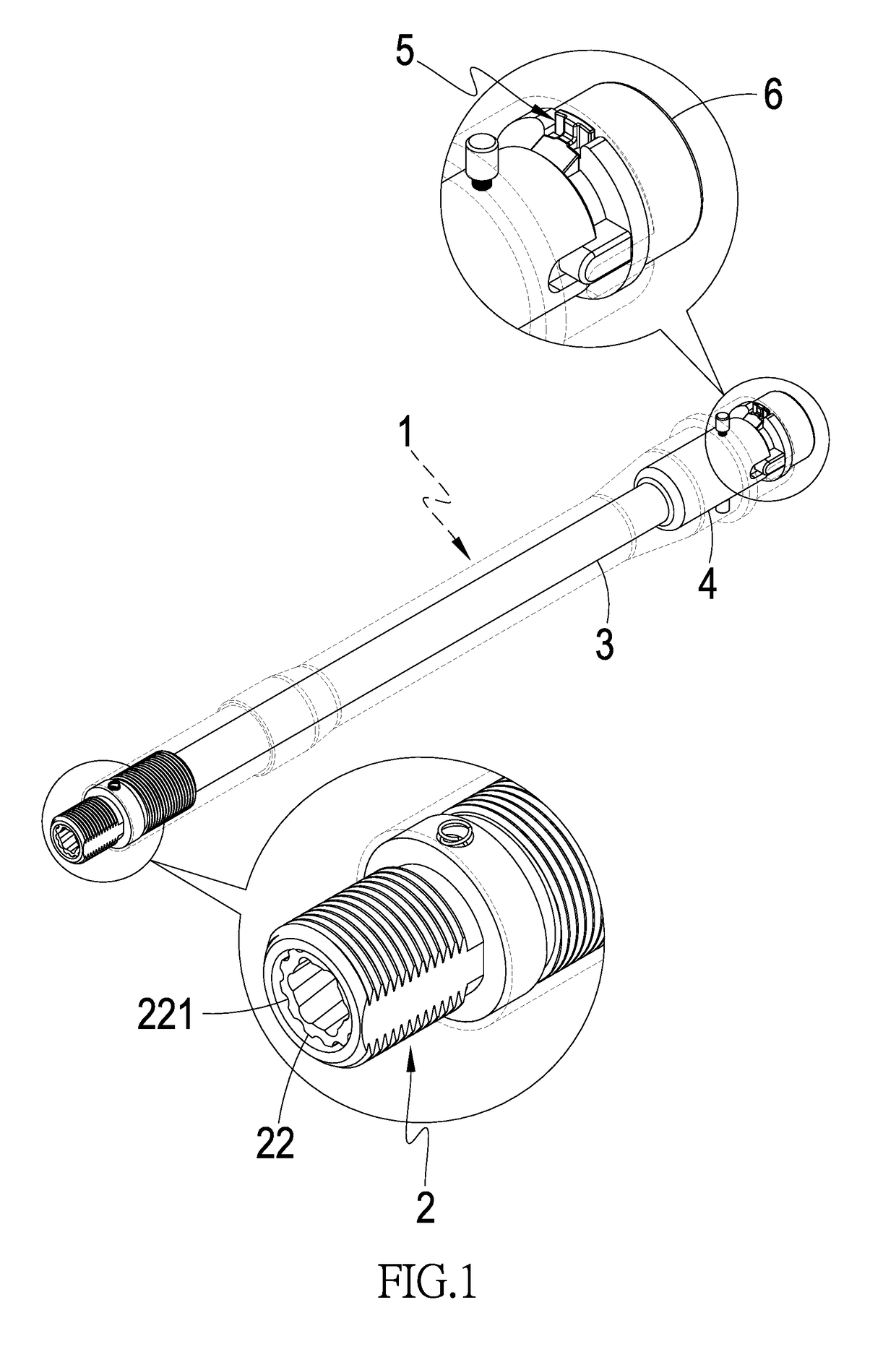
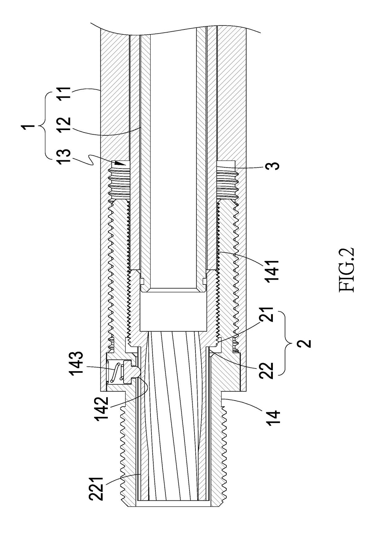
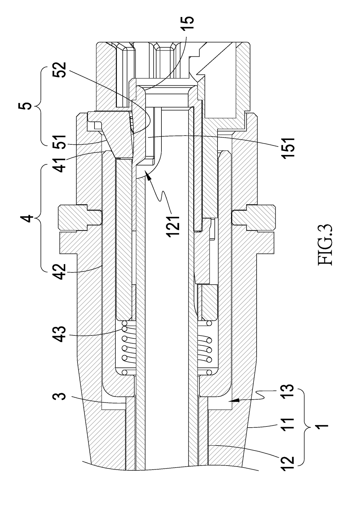
[0021]As shown in FIGS. 1-4, the present invention is mountable in mountable in a gun barrel 1 and the gun barrel 1 comprises an external barrel member 11, an internal barrel member 12 arranged in the external barrel member 11 for a BB bullet to move therein, and at least one movement space 13 formed between the external barrel member 11 and the internal barrel member 12. A main structure of the present invention comprises the following:

[0022]an adjustment assembly 2, which is mounted to a front end...


PUM


Abstract

A structure is mounted in a gun barrel and includes an adjustment assembly arranged at a front end of the gun barrel, a connection tube arranged in the gun barrel in abutting engagement with the adjustment assembly to be driven by the adjustment assembly for movement, a plurality of thread sections formed on the adjustment assembly and in threading engagement with the gun barrel for fine adjustment of the adjustment assembly, at least one transmission sleeve arranged at one end of the connection tube that is distant from the adjustment assembly, and a press-down member arranged at one side of the transmission sleeve to be abutted on by the transmission sleeve for pressing inwardly of the gun barrel.

Description

TECHNICAL FIELD OF THE INVENTION[0001]The present invention relates generally to a combination of a trajectory adjustment structure with a gun barrel to provide a trajectory adjustment structure that allows for stable and precise adjustment of a hop-up force applied to a projectile.DESCRIPTION OF THE PRIOR ART[0002]To allow a projectile of toy gun to maintain stable flying after being driven out of a barrel by pressurized gas, it is common to apply a hop-up force to the projectile.[0003]A conventional hop-up adjustment mechanism is mounted outside the gun barrel and is fixed at a rear end part of the gun barrel. When it comes the need to replace the gun barrel, the hop-up adjustment mechanism must be removed first before the replacement can be conducted. It may occasionally occur that the replacement of gun barrel cannot be correctly carried out due to difference of design. Further, the conventional hop-up adjustment mechanism involves an adjustment means that is rough and adjustmen...

Claims


Application Information

Patent Timeline
Patent Type & Authority Patents(United States)
IPC IPC(8): F41B11/00F41B11/70F41B11/89
CPCF41B11/89F41B11/70F41A21/10F41A21/16F41B7/08
Inventor LIAO, YIN-HSI
Owner GUAY GUAY TRADING CO LTD
Why Eureka
Try Eureka